Franklin Fueling Systems LS500 Auto Learn Line Leak Detection Installation & Users Guide User Manual
Page 6
6
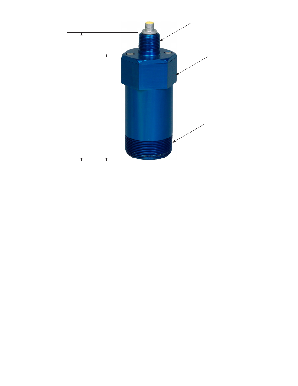
Figure 2: TS-LSU500 Dimensions
6.25"
(159 mm)
5.13"
(130 mm)
2" NPT
3/4" NPT
2-3/8" (70mm)
across flats
Definitions and Acronyms
AIM – 4-20mA Analog Input Module (Intrinsically Safe)
FMS – Fuel Management Systems
IS – Intrinsically Safe
ISD – In-Station Diagnostic
LCD – Liquid Crystal Display
LED – Light Emitting Diode
LLD – Line Leak Detection
PC – Personal Computer
PM – Probe Module (Intrinsically Safe)
RM – Relay Module
SCM – Secondary Containment Monitoring
STP – Submersible Turbine Pump
TPI – Turbine Pump Interface
T5 – T5 Series FMS Consoles
(TS-5 / 608, TS-550 EMS, TS-5000 / EXPC
/ TS-550evo)
TS-EMS – Environmental Monitoring System
TSA – TankSentinel Anywhere
Transducer Installation
1. Apply UL Classified Gasoline / Oil resistant pipe dope thread sealant to the threads of the LSU500 Transducer and
use a 2
3
/
8
” open-end wrench to install it in the Leak Detector Port of the STP housing
(see Figure 1).
2. Install Couplings, threaded Rigid Metal Conduit (RMC), and Explosion / Weather Proof Junction Boxes (J-Boxes)
in the STP sumps. For intrinsically safe wiring, run the transducer lead to the junction box. For explosion-proof
installations, run conduit to the top of the transducer.
3. Install threaded RMC and EYS fittings along with Transducer Cables (Belden #9365) from LS500 console to
the Explosion / Weather Proof J-Boxes. A licensed electrician should splice the cables together. If this wiring is
Intrinsically Safe it MUST NOT be run with any Explosion-Proof wiring or other non-Intrinsically safe wiring!
Alpha cable #58411 (INCON #600-0062) must be used if using nonmetallic (PVC) conduit as allowed by local code.