Turbine pump interface (tpi) applications – Franklin Fueling Systems LS500 Auto Learn Line Leak Detection Installation & Users Guide User Manual
Page 12
12
Turbine Pump Interface (TPI) Applications
In systems where TPI is used, the relays are not needed for line leak or STP operation. Communication with the FFS
smart controllers is done exclusively by the RS-485 connection. Refer to the Programming Manual for full TPI instructions.
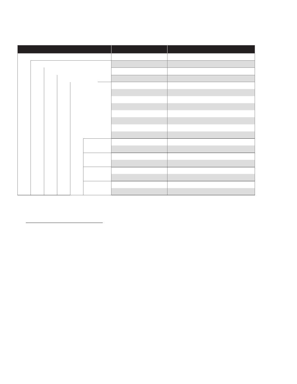
Example: TPI Setup
Group Name
Parameter Name
Parameter Value
Power Supply
RS-485
Enable Interface Yes
TS-TPI
Enable Interface Yes
Controllers
A
Number of Controllers 3
Controller 1
Name Unleaded Controller
Enabled Yes
Type Mag/Eco
Address 1
Group 0
Tank 1
Height 5.00 in
* Number of inputs 4
Input 1
Type 4-20 mA Input Module
Channel Unleaded Transducer
Input 2
Type AC Input Module
Channel Dispenser 1 Unleaded Hook Signal
Input 3
Type AC Input Module
Channel Dispenser 2 Unleaded Hook Signal
Input 4
Type AC Input Module
Channel Dispenser 3 Unleaded Hook Signal
* Calculate the total number of inputs that need to turn on the STP:
1 transducer
+ Number of AC inputs for the specific line
+ Any other inputs to operate the STP
= Total number of inputs
Note: Height is the estimated distance from PMA bottom to tank bottom. This distance is used for empty tank and high
water conditions.
- S940 (8 pages)
- Data Modem / Data Fax Modem for Tank Sentinel, AutoStik, & BulkStik ATGs (1 page)
- Tank Sentinel (TS-1001, 2001, 504, & 508) Setup Programming Guide (184 pages)
- Tank Sentinel (TS-1001, 2001, 504, 508 & 750) Setup Programming Guide (184 pages)
- Main System Board for Tank Sentinel, AutoStik, BulkStik ATGs (4 pages)
- TS-ROM2 (8 pages)
- Memory Backup Battery for Tank Sentinel, AutoStik, & BulkStik ATGs (2 pages)
- Tank Sentinel Quick Reference Guide (2 pages)
- Tank Sentinel (Except TS-2001), AutoStik Jr, BulkStik, AutoStik II (1-4 Ch) Display & Keypad Assembly (P/N 010-0087) (1 page)
- Tank Sentinel (TS-1001, 2001, 504, 508 & 750) Operators Guide Rev. D (100 pages)
- Tank Sentinel, AutoStik, BulkStik Printer Assembly (P/N 020-3050) (1 page)
- Tank Sentinel (TS-1001, 2001, 504, 508 & 750) Operators Guide Rev. C (100 pages)
- Tank Sentinel (TS-1001, 2001, 504, 508 & 750) Installation (98 pages)
- TS-1001, BulkStik, AutoStik (except AutoStik II 8Ch) Ribbon Cable (P/N 600-0077 & 600-0032) (1 page)
- TS-STS Sump Test System Kit (8 pages)
- TS-DTU Noise Suppression Cables TS-DRK (10 pages)
- Console DTU (Data Transfer Unit) (4 pages)
- TS-DTU Data Transfer Unit Dispenser Retrofit Manual (40 pages)
- Colibri One Pulse Relay Rule Setup (1 page)
- Colibri CL6 Installation Guide (12 pages)
- Colibri CL6 Setup and Operators Guide (32 pages)
- Colibri System Board Replacement (2 pages)
- Colibri Quick Reference (2 pages)
- Colibri: Connecting a T5 Series Fuel Management System or Colibri Tank Monitor to an ALVIC SCS3 Point of Sale System (3 pages)
- T5 Series Fuel Management System Installation Guide (30 pages)
- TS-550/TS-5000 consoles Secondary Containment Monitoring (28 pages)
- TS-550/TS-5000 Retrofit Printer Installation (1 page)
- T5 Series Fuel Management System Operators Guide (46 pages)
- T5 Series Fuel Management System Operators Guide (48 pages)
- T5 Series Fuel Management System Programming Guide (66 pages)
- T5 Series Fuel Management System Quick Reference Guide (2 pages)
- T5 Retrofit LCD Display Installation (1 page)
- T5 Tank Sentinel Programming Guide (48 pages)
- TSSP-TMPTR Thermal Printer (8 pages)
- TS 550 evo Fuel Management System Operators Guide (48 pages)
- TS 550 evo Fuel Management System Installation (28 pages)
- TS 550 evo Fuel Management System Quick Reference Guide (2 pages)
- TS 550 evo Fuel Management System Programming Guide (54 pages)
- TS-550 evo MODBUS Installation & Setup (22 pages)
- TS-LLD Changing the TS-LLD Control Unit (1 page)
- TS-LLD Changing the TS-LLD LSU Filter Screen or O-Ring (1 page)
- TS-LLD Leak Detection Sensor – Cleaning & BriteSensor Recovery (2 pages)
- TS-LLD Field Verification : Functional Testing of the INCON TS-LLD (2 pages)
- TS-LLD Changing the TS-LLD Control Unit Faceplate (1 page)
- TS-LLD Changing the TS-LLD 1 microfarad Line Filter Capacitor (1 page)