Franklin Fueling Systems T5 Series Fuel Management System Operators Guide User Manual
Page 34
30
FMS
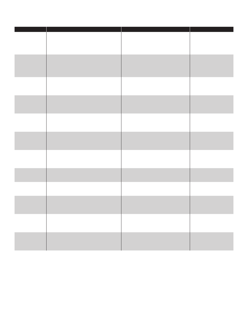
Probe Alarms
Displayed Alarm
Description
Recommended Actions
Reference Source
Float Height
Error
A float on the probe listed with the alarm is
being monitored at a varying height outside
of thresholds. Causes can include broken
float and programming, or mistakenly
associating a gasoline and diesel float.
Verify Probe programming. Visually
inspect that the probe float type matches
the type of product. Inspect magnet and
probe shaft for cracks or debris and
clean if necessary.
Probes Setup in
Programming Manual)
/ Applicable Equipment
Guide*
Float Missing
A float on the probe listed with the alarm
has not been detected or the probe was
programmed with the incorrect number of
floats.
Verify the ‘number of floats’ in Probe
programming. Number of floats must
match number of floats installed. Float
must be lower than 5" from the bottom of
the probe head.
Probes Setup in
Programming Manual /
Applicable Equipment
Guide*
High Water
Level
The water float on the Tank/Manifold listed
with the alarm is above the programmed
High Water Level Limit.
Verify that the programmed limit is
correct. Verify that the Water Level
values on the console correspond with
the actual water level in the tank.
Probes Setup in
Programming Manual /
Applicable Equipment
Guide*
High Product
Level
The product float on the Tank/Manifold listed
with the alarm is above the programmed
High Product Level Limit. Tank may be close
to an overfull condition.
Verify that the programmed limit is
correct. Verify that the Gross Product
Level values on the console correspond
with actual product level in the tank.
Probes Setup in
Programming Manual /
Applicable Equipment
Guide*
High High
Product Level
The product float on the Tank/Manifold listed
with the alarm is above the programmed
High High Product Level Limit. Tank may be
near an overfull condition.
Verify that the programmed limit is
correct. Verify that the Gross Product
Level values on the console correspond
with actual product level in the tank.
Probes Setup in
Programming Manual /
Applicable Equipment
Guide*
Low Product
Level
The product float on the Tank/Manifold listed
with the alarm is above the programmed
Low Product Level Limit. Tank may be close
to an empty condition.
Verify that the programmed limit is
correct. Verify that the Gross Product
Level values on the console correspond
with actual product level in the tank.
Probes Setup in
Programming Manual /
Applicable Equipment
Guide*
Low Low
Product Level
The product float on the Tank/Manifold listed
with the alarm is above the programmed
Low Low Product Level Limit. Tank may be
near an empty condition.
Verify that the programmed limit is
correct. Verify that the Gross Product
Level values on the console correspond
with actual product level in the tank.
Probes Setup in
Programming Manual /
Applicable Equipment
Guide*
No Probe
Detected
This alarm indicates a communication error
between the console and the probe listed
with the alarm.
Verify Probe programming. Inspect the
probe wiring from the probe module to
the probe.
Probes Setup in
Programming Manual /
Installation Guide
Probe
Synchronization
Error
This alarm indicates a communication error
between the console and the probe listed
with the alarm.
Verify Probe programming. Inspect the
probe wiring from the probe module to
the probe.
Probes Setup in
Programming Manual /
Installation Guide
RTD Table Error The RTD Table programmed for the probe
listed with the alarm is incorrect.
Verify the RTD Table programming.
Probes Setup in
Programming Manual /
Applicable Equipment
Guide*
Temperature
Error
This alarm indicates a temperature sensor
error or failure inside the probe shaft of the
probe listed with the alarm.
Verify the RTD Table programming.
Visually inspect probe shaft for defects
and cracks.
Probes Setup in
Programming Manual /
Applicable Equipment
Guide*
Unstable Probe This alarm indicates inconsistent data from
the probe listed with the alarm.
Inspect the probe wiring from the probe
module to the probe. Verify that the
product in the tank is both physically and
thermally stable.
Installation Guide /
Applicable Equipment
Guide*
* Bulletins and the T5 Series Installation Guide (p/n 000-2150) and the T5 Series Programming Manual (000-2142) can be found on
Franklin Fueling’s web site - http://www.franklinfueling.com/service/. Select Technical Documentation / Fuel Management System