Appendix b – alarm table, System – Franklin Fueling Systems T5 Series Fuel Management System Operators Guide User Manual
Page 31
27
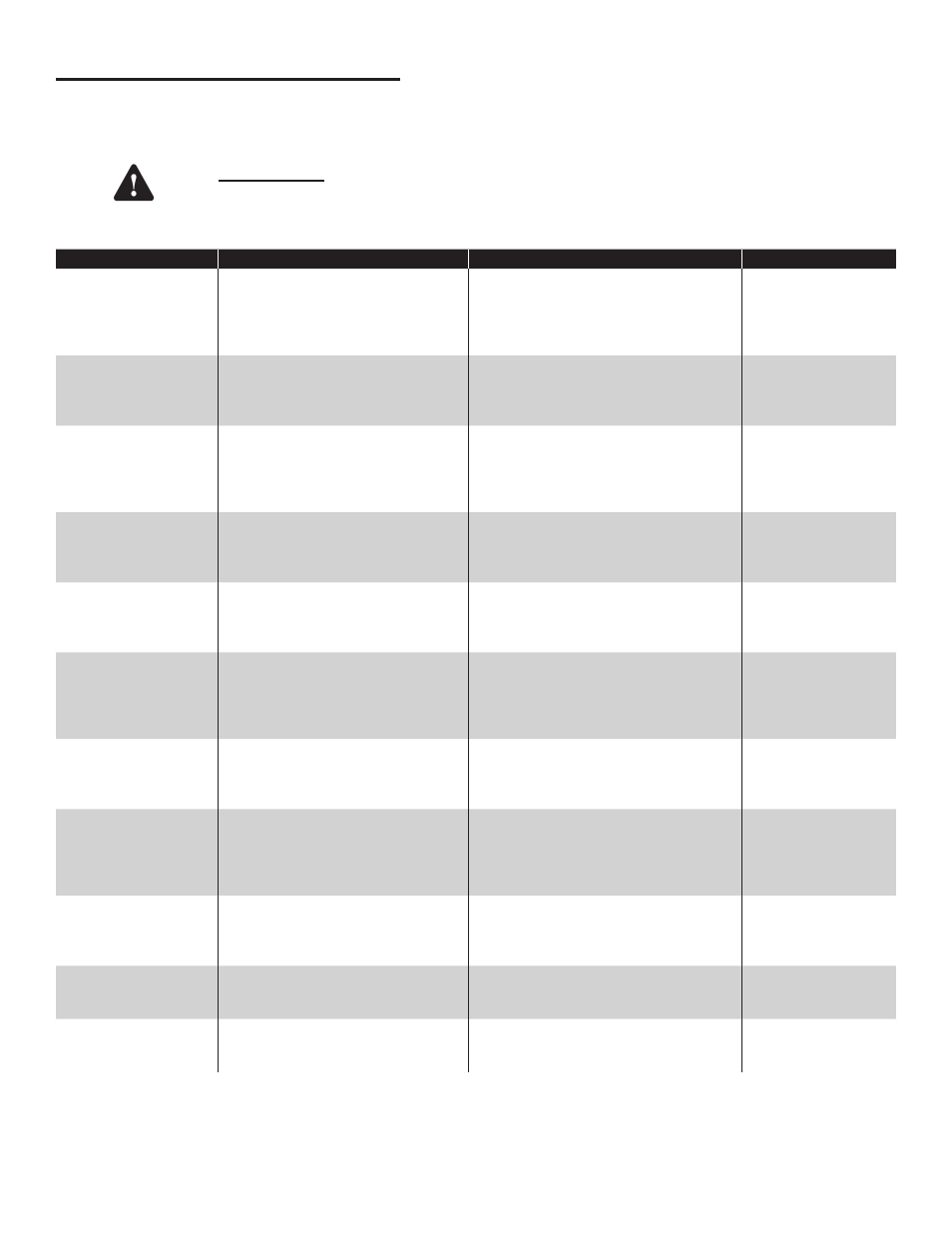
Appendix B – Alarm Table
Note: Refer to Safety Instructions outlined in this manual prior to performing any maintenance on or inside the console.
Note: If at any time while troubleshooting a Warning or Alarm this guide does not correct the issue, contact FFS Technical
Services.
Warning
Always remove power from the console prior to installing or removing a module or performing any
maintenance while the console door is open.
System
Displayed Warning
Description
Recommended Actions
Reference Source
2-Wire Sensor Module
Is Offline
The specified 2-Wire Sensor Module
listed with the alarm has experienced
a problem or may not be recognized
by the Controller Module.
Cycle power to the console. Visually
verify that the green ‘RUN’ light on the
applicable 2-Wire Sensor Module is on
continuously after the system boot is
complete.
Installation Guide /
Applicable Bulletins*
2-Wire Sensor Module
Number Mismatch
The number of expected 2-Wire
Sensor Modules does not equal the
number of 2-Wire Sensor Modules
installed.
Verify the physical number of 2-Wire
Sensor Modules installed and compare
with the number of 2-Wire Sensor
‘Modules Expected’ in the programming.
General Setup in
Programming Manual
/ Applicable Bulletins*
3-Wire Sensor Module
is Offline
The specified 3-Wire Sensor Module
listed with the alarm has experienced
a problem or may not be recognized
by the Controller Module.
Cycle power to the console. Visually
verify that the green ‘RUN’ light on the
applicable 3-Wire Sensor Module is on
continuously after the system boot is
complete.
Installation Guide /
Applicable Bulletins*
3-Wire Sensor Module
Number Mismatch
The number of expected 3-Wire
Sensor Modules does not equal the
number of 3-Wire Sensor Modules
installed.
Verify the physical number of 3-Wire
Sensor Modules installed and compare
with the number of 3-Wire Sensor
‘Modules Expected’ in the programming.
General Setup in
Programming Manual
/ Applicable Bulletins*
4-20mA Input Module
Error
Input amperages have exceeded their
thresholds—this Error applies to the
4-20mA Input Module listed with the
alarm.
Troubleshoot external 4-20mA device and
wiring from the module and channel of the
4-20mA Input Module listed with the alarm.
Applicable Equipment
Guide(s)*
4-20mA Input Module
is Offline
The specified 4-20mA Input Module
listed with the alarm has experienced
a problem or may not be recognized
by the Controller Module.
Cycle power to the console. Visually
verify that the green ‘RUN’ light on the
applicable 4-20mA Input Module is on
continuously after the system boot is
complete.
Installation Guide /
Applicable Bulletins*
4-20mA Input Module
Number Mismatch
The number of expected 4-20mA Input
Modules does not equal the number of
4-20mA Input Modules installed.
Verify the physical number of 4-20mA
Input Modules installed and compare with
the number of 4-20mA Input ‘Modules
Expected’ in the programming.
General Setup in
Programming Manual
/ Applicable Bulletins*
AC Input Module
is Offline
The specified AC Input Module listed
with the alarm has experienced a
problem or may not be recognized by
the Controller Module.
Cycle power to the console. Visually
verify that the green ‘RUN’ light on
the applicable AC Input Module is on
continuously after the system boot is
complete.
Installation Guide /
Applicable Bulletins*
AC Input Module
Number Mismatch
The number of expected AC Input
Modules does not equal the number of
AC Input Modules installed.
Verify the physical number of AC Input
Modules installed and compare with the
number of AC Input ‘Modules Expected’ in
the programming.
General Setup in
Programming Manual
/ Applicable Bulletins*
IO Input Alarm
The input senses either voltage pres-
ent or no voltage. This alarms when
input voltage is not as programmed
Verify that programming parameters
meet site specification. Check all wiring
associated with the input at fault.
Installation Guide /
Applicable Bulletins*
IO Module Number
Mismatch
The number of expected IO modules
does not equal the number of IO
modules installed
Verify the physical number of IO modules
installed and compare with the number of
IO modules programmed.
Installation Guide /
Applicable Bulletins*
* Bulletins and the T5 Series Installation Guide (p/n 000-2150) and the T5 Series Programming Manual (000-2142) can be found on
Franklin Fueling’s web site - http://www.franklinfueling.com/service/. Select Technical Documentation / Fuel Management Systems