Relay output wiring (optional), Emergency generator applications (optional), Figure b-3 – alarm output wiring schematic – Franklin Fueling Systems T5 Series Fuel Management System Installation Guide User Manual
Page 16
16
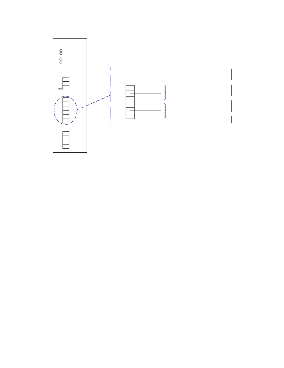
Relay Output Wiring (optional)
As illustrated in the diagram below, the Power Supply Module’s two relay outputs can be used to activate an external
alarm (TS-RA2) and the two inputs can be used to silence that alarm remotely (TS-RK).
Note: The TS-RA2, TS-RA1 and TS-RK are not part of the UL certification of this system.
Emergency Generator Applications (optional)
The wiring or use of discrete inputs is optional — skip this section if you don’t plan to use this interface. Discrete inputs
may be wired to a T5 series console with 18 AWG, type TFFN or THWN wire. You may also use THHN wire in sizes larger
than 18 AWG.
Emergency backup power generator run-relay(s) are wired to the discrete input interface terminals at the T5 series
console. A run-relay closure will stop a leak test on the associated generator fuel tank. When the generator run-
relay opens (generator stops running), a run report is produced at the console, which shows the total and hourly fuel
consumption rate during the run cycle.
Note: You must use dry run-relay contacts for this interface because the T5 series supplies +5 VDC digital logic power at
the IN (input) terminals.
Note: It is recommended that you use: IN 1 & GND for Generator 1 /fuel supply Tank #X, and IN 2 & GND for Generator 2
/fuel supply Tank #Y. The specific fuel tank(s) assigned are “programmable.” See Figure B-4 for wiring details.
Enlarged View of Power Supply Module’s Relay Outputs
NC1
C1
NO1
NC2
C2
NO2
Suggest Use - Optional:
INCON TS-RA1 (or TS-RA2) & TS-RK
Remote tank overfill alarm outputs.
See the appropriate manuals for further
details.
Remote/External Alarm Outputs
Power Supply
Module
RUN
ERR
5V
24V
POWER
L1
N/L2
RELAY OUTPUTS
NC1
C1
NO1
NC2
C2
NO2
LOW VOLTAGE INPUTS
IN1
GND
IN2
GND
Figure B-3 – Alarm Output Wiring Schematic