Appendix b: power supply module (ps) – Franklin Fueling Systems T5 Series Fuel Management System Installation Guide User Manual
Page 14
14
Appendix B: Power Supply Module (PS)
The PS is a non-intrinsically safe module that provides power to the T5 series console from line voltage rated 110 - 240
VAC. The PS is two inches wide, occupies two slots and is located immediately to the right of the CM. The PS consists of
two AC/DC switching power supplies - one switching power supply is +5V and the other is +24V.
The PS also has two relay outputs for use with remote annunciators and two low voltage inputs for emergency generator
applications. An example of a remote annunciator setup can be found in Figure B-3 and an emergency generator
application setup can be found in Figure B-4.
Line Power Wiring
At the electrical power panel, use or install a 20 amp circuit breaker — this breaker should be dedicated to only supplying
power to the T5 series console. Mark this circuit “T5 series console [power] - ONLY” on the circuit label (at the back of the
electrical power panel door). Refer to Figure B-1 and the 110/240 VAC Line Power Wire Connection List that precedes it
for line power wiring information.
Note: Avoid connecting other equipment to this circuit. If other equipment is connected to this dedicated circuit, the
resulting electrical noise could cause faulty system operation.
Make sure that the T5 series console’s power circuit breaker is turned off during any installation.
Lethal voltages are present inside the console which could kill or injure you. Also, secure the T5
series console’s circuit breaker in the off position and attach a “lockout” to it, which is dated and
signed by you, to prevent accidental closure, injury or death.
The ground bus in the electrical panel must be connected to an earth ground as required by the
National Electrical Code (or Canadian Electrical Code) when applicable. If the ground bus is not
properly connected to an earth ground or if the IS safety ground is not properly connected at the
console, a dangerous condition will be created which could result in an explosion.
Check Electrical Resistance to Earth Ground
After wiring the IS safety grounds, check the resistance between the IS safety ground terminals at the console and the
earth ground – this resistance must be less than 1 ohm.
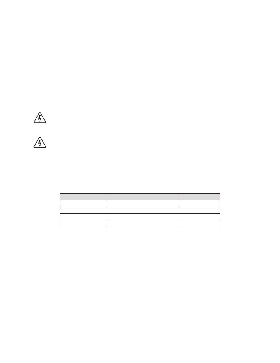
110/240 VAC Line Power Wire Connection List
Electrical Panel
No. Conductors, Color (Gauge)
Circuit
20 Amp Circuit Breaker 1 Black wire, 14 AWG (1.6 mm) min.
110/240 VAC Power
Neutral
1 White Wire, 14 AWG (1.6 mm) min. Neutral
Ground Bus
1 Green wire, 14 AWG (1.6 mm) min. Ground
Ground Bus
1
Green wire, 12 AWG (2.1 mm) min.
Safety Ground
Danger
Danger