System 4 with multiple system 8/10 p, Switchers – Extron Electronics System 8_10 Plus User Manual
Page 47
Extron • System 8/10 P
LUS
• User’s Manual
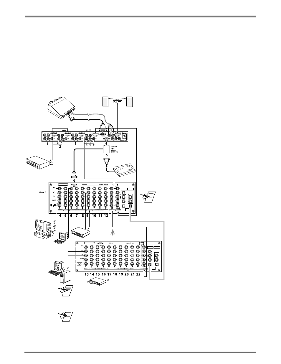
Multiple Switcher Operation
Looping with System 4
xi
5-8
System 4 with Multiple System 8/10 P
LUS
Switchers
This configuration will work only with System 8/10 P
LUS
switchers in a Daisy
Chain configuration. The master of the System 8/10 P
LUS
chain must be
configured in the “RS-232 only” projector communications mode. The System 4
will control the System 8/10 P
LUS
Switcher through the secondary RS-232 port by
way of a System 4 Slave Adapter described on page 4-2 of the System 4 User’s
Manual. The System 4 communicates with the first System 8/10 P
LUS
which in
turn communicates with the second System 8/10 P
LUS
.
A. Use the Slave Adapter described in the System 4 manual to connect the
controlling device to the System 4 and to the first System 8/10 P
LUS
.
B. Connect one cable end from the Intercom Out connector (RJ11) on the first
System 8/10 P
LUS
and the other end into the Intercom In
connector (RJ11) of the second System 8/10 P
LUS
.
C. Connect the RGBHV and Audio outputs from the
System 8/10 P
LUS
master to the last input of the
System 4. Likewise, connect the output of the second
slave to the last input of the first slave.
Go to page 5-9 to set up the System 8/10 P
LUS
DIP
switches.
Regardless of how the slave switcher input connectors
are marked, they must conform to the inputs of the
System 4. They are: R/C, G/Y/Video, B, H/HV & V. Note
that composite video uses the G/Y connector.
After making all the cable connections, go to page 4-7 of
the System 4 User’s Manual to configure the master/
slave as a system.
Important audio information! If balanced audio
connections are made from the System 8/10
P
LUS
audio output to the System 4 audio input, there
will be +6 dB of gain. This gain can be offset with a 6 dB
pad. If the level of gain does not exceed
the System 4 maximum input level, the
level can be offset with the System 4 audio
gain/cut menu. However, if audio
connections are made unbalanced, there is
no gain.
_____ The audio attenuator(s) on the System 8/10 P
LUS
audio inputs should be set to 0
dB cut by turning the attenuator clockwise until it stops. This will set all input
audio levels on the System 4. Refer to the System 4 User Manual for audio
setup.
_____ Nine audio connectors are shipped with each System 8 P
LUS
and eleven with
each System 10 P
LUS
. If more are needed, use Phoenix® audio connectors,
Extron part number 10-163-01.
OUTPUT
see notes and page 2-6
concerning audio connections