Extron Electronics System 8_10 Plus User Manual
Page 26
Extron • System 8/10 P
LUS
• User’s Manual
Rear Panel Connections
Video Loop Back
2-11
VLB Operation
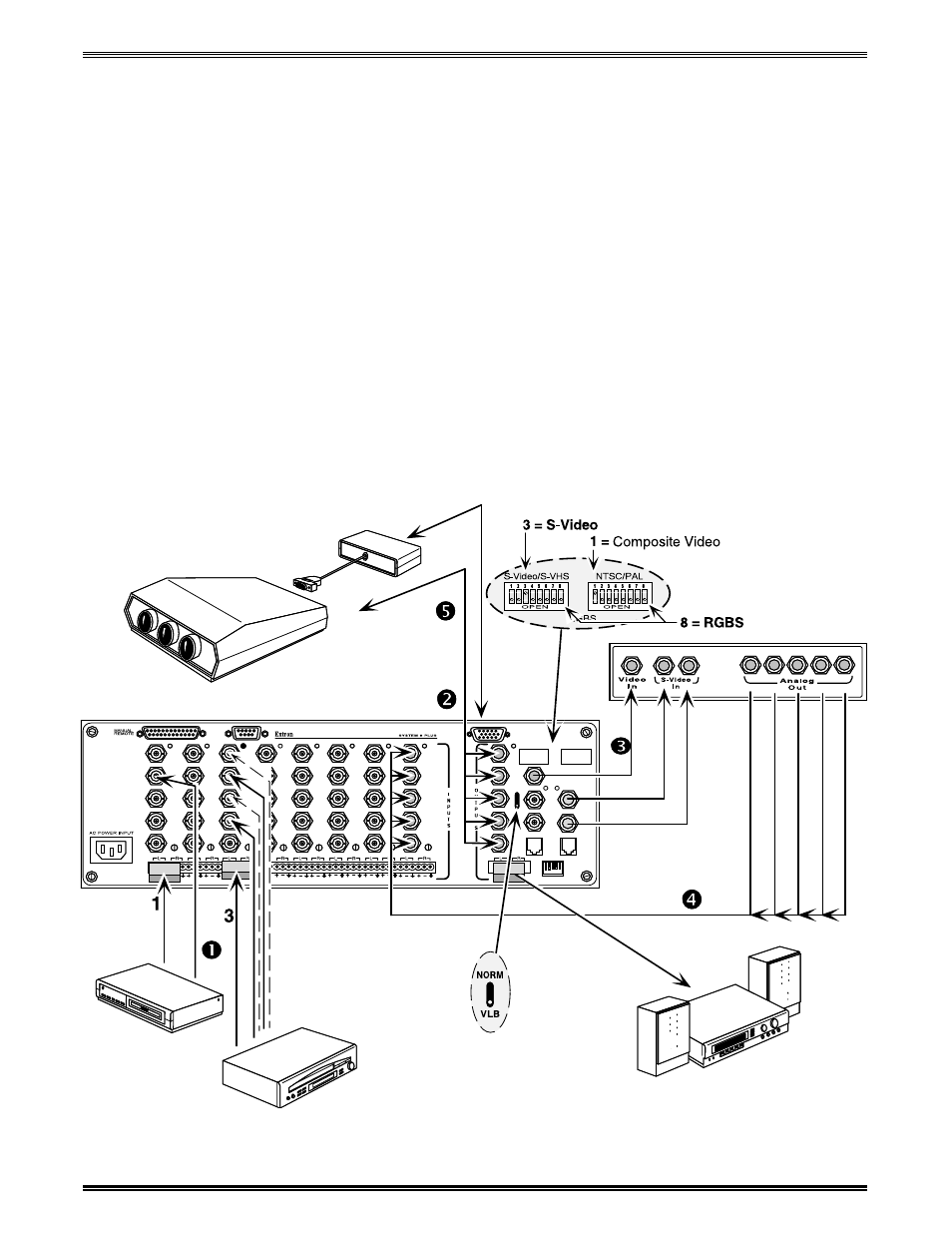
The illustration below is an example of a decoder being used in Video Loop
Back, however, it could be any one of several types of decoders or line doublers.
When VLB is active, the System 8/10 P
LUS
operates as follows:
1. Composite video and S-Video sources are connected to any of the System 8/10
P
LUS
inputs except the last one.
2. Standard RGB inputs exit the switcher through the normal RGB output.
3. Composite Video or S-Video signals exit the switcher through their normal
Composite video or S-Video outputs and are routed to the external decoder or
scan doubler.
4. The RGBS output of the decoder or scan doubler is then “looped back” to the
last input (input #8 or #10) of the switcher, which is selected at the same time.
5. The RGBS output from the switcher goes to the projector.
This allows the System 8/10 P
LUS
to route only RGB signals to the display
device.
- FOX Matrix 3200 (132 pages)
- ADA 2-4-6 Series (3 pages)
- ADA 6 Component (2 pages)
- AVT 100 (37 pages)
- AVT 200HD Setup Guide (4 pages)
- AVT 200HD User Guide (118 pages)
- AVTrac (482) User Guide (28 pages)
- CAT 5 Receivers (15 pages)
- CAT 5 Transmitters (15 pages)
- CD 400 (3 pages)
- CD 800 (15 pages)
- CD 900 (19 pages)
- CD 100 (18 pages)
- CSVEQ 100 D (2 pages)
- CSVEQ 100 D (38 pages)
- DA RGB_YUV Series (17 pages)
- CVEQ1, CVEQ1 WM, CVEQ1 AAP (17 pages)
- CVEQ_SVEQ 100 Series Setup Guide (2 pages)
- CVDA 6 EQ MX (3 pages)
- CVDA 6 EQ MX (2 pages)
- CVC 300 (8 pages)
- CVC 200 (4 pages)
- CVC 100 (2 pages)
- DDS 402 (54 pages)
- DDS 100 (54 pages)
- DA AV EQ Series (2 pages)
- DVC 501 SD User Guide (38 pages)
- DVC 501 SD Setup Guide (2 pages)
- DTP T USW 333 User Guide (26 pages)
- DTP T USW 333 Setup Guide (4 pages)
- DTP T USW 233 User Guide (26 pages)
- DTP T USW 233 Setup Guide (4 pages)
- DTP HDMI 330 User Guide (19 pages)
- DTP HDMI 330 Setup Guide (2 pages)
- DTP HDMI 301 User Guide (23 pages)
- DTP HDMI 301 Setup Guide (2 pages)
- DTP HDMI 230 User Guide (19 pages)
- DTP HDMI 230 Setup Guide (2 pages)
- DTP HDMI 230 D User Guide (22 pages)
- DTP DVI 330 User Guide (19 pages)
- DTP DVI 330 Setup Guide (2 pages)
- DTP DVI 301 User Guide (23 pages)
- DTP DVI 301 Setup Guide (2 pages)
- DTP DVI 230 User Guide (19 pages)
- DTP DVI 230 Setup Guide (2 pages)