Daisy chain connection – Extron Electronics System 8_10 Plus User Manual
Page 42
Extron • System 8/10 P
LUS
• User’s Manual
Multiple Switcher Operation
5-3
Daisy Chain Configuration
Daisy Chain Connection
Daisy Chain configuration refers to routing the output of the first slave (#0) into
the last input of the master switcher, and the output of the second slave (#1) into
the last input of slave #0... etc. All other inputs are used for various video
sources. The maximum number of inputs available in the daisy-chain
configuration is 154 when using all System 10 P
LUS
switchers (120 when using
all System 8 switchers). The Daisy Chain configuration is easy to configure, but
results in decreased system bandwidth due to the cascading signal path through
multiple switchers. As a further limitation of this connection scheme, it does not
allow the use of composite-to-RGB converters or scan doublers.
Looping Instructions
See illustration on the facing page as you do the following:
1. Remove power from all switchers and decide which will become the Master Unit
and which the Slave.
2. Disconnect all communications devices from the Master Unit.
_____ The Slave Units should never have any communications devices connected,
except a contact closure remote control (if required).
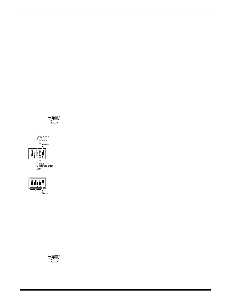
3. On the Master Unit, locate the DIP switches labeled “Address” in the lower right
corner of the rear panel. Set switches #3 and #5 up, and #1, #2 and #4 down.
(Switch #4 must be set to the “down” position until Step 9.)
4. On the first Slave Unit, locate the Address DIP switches and set switches #1, 2,
3 and 4 up (Slave # 0), and set switch #5 down, for Slave Mode.
5. Connect an RJ11 cable from the “System Intercom Out” connector of the Master
to the “System Intercom In” connector of Slave #0. If more slave units are being
connected, connect another RJ11 cable from Slave #0 “System Intercom Out” to
Slave #1 “System Intercom In”. Repeat this for each remaining slave unit in the
daisy chain.
6. Connect the video output of Slave #0 to the last input of the Master Unit.
Connect the output of Slave #1 to the last input of Slave #0. Repeat this for each
remaining slave unit in the daisy chain.
7. Connect any communication devices (e.g., projector control cable, remote
control, etc.) to the Master Unit.
8. Connect the video outputs from the Master Unit to the video inputs of the
projector. Refer to Chapter 3 for detailed procedures.
9. To save the configuration first turn the Slave On, and then turn the Master On.
Wait at least 10 seconds for the Master Unit to save the configuration to memory.
10. On the Master Unit, set Address switch #4 to the Normal, or “Up” position.
11. Make any necessary connections and put all switchers to normal operation.
_____ Video Loop Back (VLB) mode cannot be used when units are connected in this
configuration.
Address
(#0)