System 4 with one system 8/10 p, Switcher, Multiple switcher operation – Extron Electronics System 8_10 Plus User Manual
Page 46: Looping with system 4 xi
Extron • System 8/10 P
LUS
• User’s Manual
Multiple Switcher Operation
5-7
OUTPUT
INPUT 1
INPUT 2
INPUT 3
INPUT 4
see notes and page 2-6
concerning audio connections
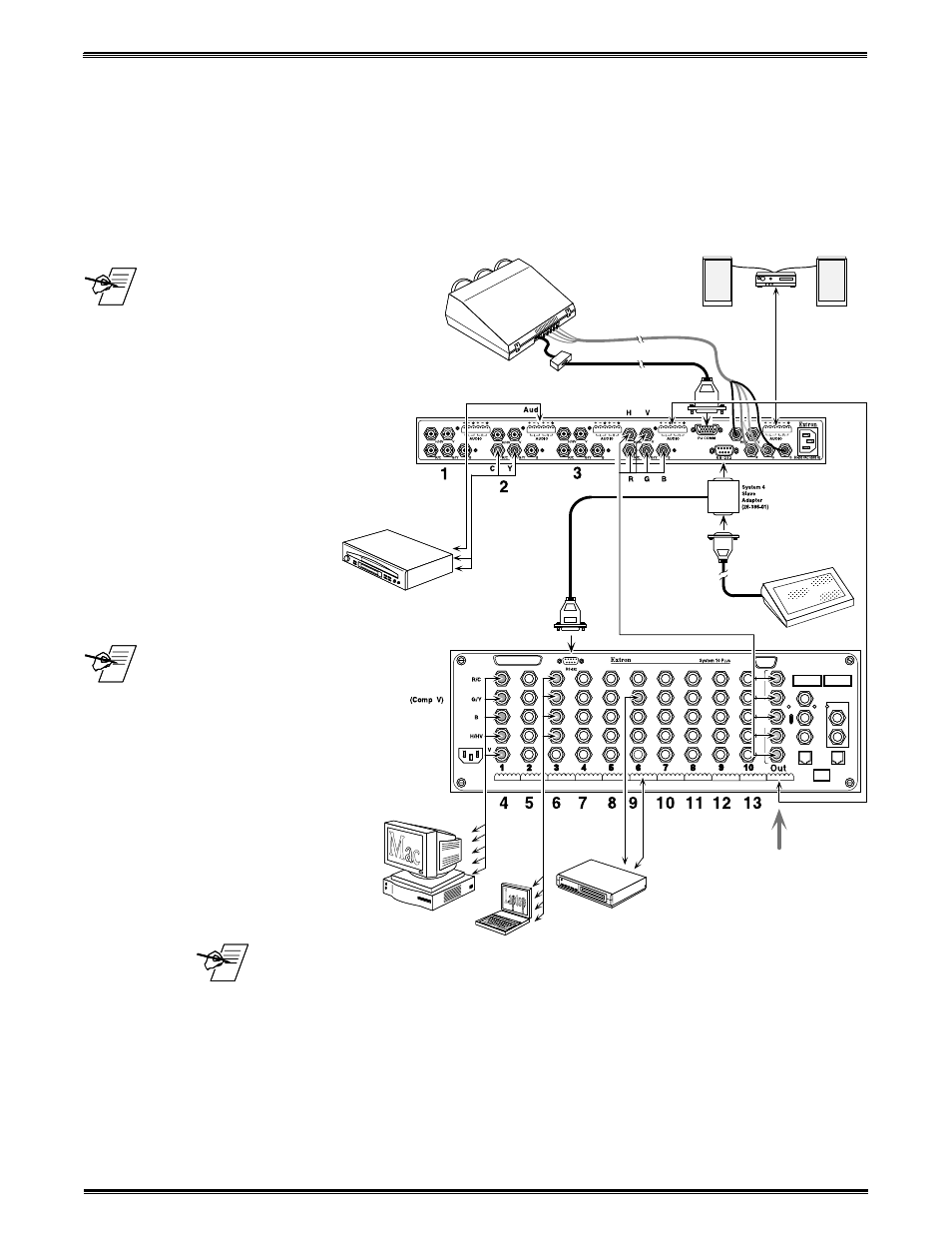
System 4 with One System 8/10 P
LUS
Switcher
The System 8/10 P
LUS
must be configured as a System 4 Slave. Connect the
RGBHV and Audio output of the System 8/10 switcher to the last (4th) input of
the System 4. Use the figure below as an example.
The System 4 will control the System 8/10 P
LUS
Switcher through the secondary
RS-232 port, by way of a System 4 Slave Adapter described in the System 4
User’s Manual.
Important audio
information! If balanced
audio connections are
made from the System 8/
10 P
LUS
audio output to the
System 4 audio input,
there will be +6 dB of gain.
This gain can be offset with
a 6 dB pad. If the level of
gain does not exceed the
System 4 maximum input
level, the level can be
offset with the System 4
audio gain/cut menu.
However, if audio
connections are made
unbalanced, there is
no gain.
The audio
attenuator(s) on the
System 8/10 P
LUS
audio inputs should be
set to 0 dB cut by
turning the attenuator
clockwise until it stops.
This will set all input
audio levels on the
System 4. Refer to the
System 4 User Manual
for audio setup.
_____
Nine audio connectors are shipped with each System 8 P
LUS
and eleven with
each System 10 P
LUS
. If more are needed, use Phoenix® audio connectors,
Extron part number 10-163-01.
See previous pages to set up the System 8/10 P
LUS
DIP switches.
After making all the cable connections, go to page 4-7 of the System 4 User’s
Manual to configure the master/slave as a system.
Looping with System 4
xi