Installation, Cabling and rear panel views, Power connection – Extron Electronics IN1508 User Guide User Manual
Page 11: Video connections, Power connection video connections, Video sources to these female bnc connectors, Pin mini din connectors
Installation
This section describes the installation of the IN1508, including:
•
•
Remote Control Battery Installation
•
Cabling and Rear Panel Views
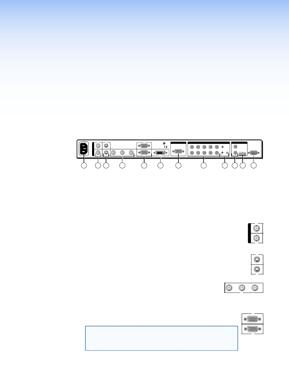
All connectors are on the rear panel (see figure 2).
50/60Hz
100-240V 50-60Hz
I
N
P
U
T
VID
VID
YC
YC
Y
B-Y
R-Y
RGB
DVI
RS-232
1
2
4
5
3
L
1
2
3
4
5
6
7
R
AUDIO INPUT
L
A
B
R
OUTPUT
L
R
OUTPUT
RGB
Y, B-Y, R-Y
8
7
8
RGB
LISTED
1T23
I.T.E.
C
U S
6
1
6
7
11
12
2
5
4
8
3
9
10
Figure 2.
IN1508 rear panel connectors
Power Connection
a
AC power connector — Plug a standard IEC power cord into this connector to connect
the switcher to a 100 to 240 VAC, 50 Hz or 60 Hz power source.
Video Connections
b
Input 1 and Input 2 composite video connectors — Connect composite
I
N
P
U
T
VID
VID
1
2
video sources to these female BNC connectors.
c
Input 3 and Input 4 S-video connectors — Connect S-video sources to these
YC
YC
4
3
YC
4-pin mini DIN connectors.
d
Input 5 component video connectors — Connect a progressive
Y
B-Y
R-Y
5
or interlaced component video (Y, B-Y, R-Y) source to these female
BNC connectors.
e
Input 6 and Input 7 RGB video connectors — Connect RGBHV or
RGB
7
RGB
6
RGBS sources to these female 15-pin HD connectors.
NOTE: On IN1508 units that ship after September 2010 and are
firmware version 2.30 or higher, inputs 6 and 7 support EDID
emulation with the default value 1024 x 768 at 60 Hz (see
“
” to select a different resolution).
IN1508 • Installation
6