9 auxiliary switches (code 9), 10 indicators, Fig. 11 closing drive with position indicator – GE Industrial Solutions GERAPID 8007R, 10007R WITH ARC CHUTES 1X2, 1X3 User Manual
Page 9: 11 solenoid closing drive (code 3), Fig. 12 closing drive with position indicator
3.2.9 Auxiliary switches (Code 9)
•
The breaker can be equipped with up to nine isolated
form C auxiliary contacts (1 NO/NC each) [Fig. 10]. The
contacts are activated by breaker’s main mechanism.
•
The contacts are wired to 15-pin control plugs: -X4 and -
X5, with 5 switches to each plug.
•
Conventional thermal current Ith=10
A. Maximum
electrical interrupting ratings for switches are 1 A/230 V
for AC15. For DC13 are 0.5 A/110 V and 0.3 A/220 V.
Fig. 10 Auxiliary switches block in the control box.
3.2.10 Indicators
Optionally, the circuit breaker can be equipped with
following indicators:
•
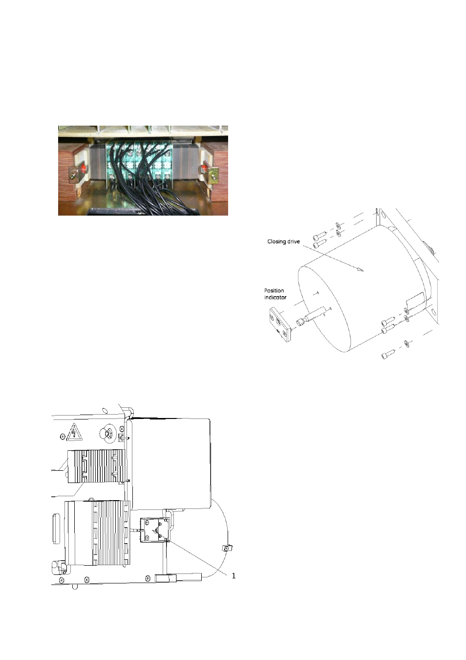
POSITION INDICATOR (Code 14) - mounted at the front of
the closing drive [Fig.
12]. Moving drive’s rod is
mechanically switching the indicator.
“OPEN” or “O” – means open main contacts
“CLOSED” or “I” – means closed main contacts
•
OC TRIP TARGET (Code 10) – a potential free, NO contact
mounted at the top of the OCT [Fig. 14]. Provides a signal
when OCT trips.
•
ARC CHUTE INDICATOR (Code 17) – a potential free, NO
contact mounted on the sidewall, item (1) on Fig. 11. Locks
electrically the closing drive when arc chute is not
installed on. The signal is available at terminal –X3 :12:13.
Fig. 11 Closing drive with position indicator.
3.2.11 Solenoid closing drive (Code 3)
•
The closing drive is mounted at the front of the breaker
and is encased in a grounded casing [Fig. 12].
•
The closing drive includes a self-interrupt control circuit
(SU PCB). This circuit enables a short activation with
minimum command duration of approximately 100ms,
causing the voltage applied to the solenoid to be switched
off after approximately 400ms and prevents, during
continuous operation, repeated reclosing (anti-pumping)
due to an existing short circuit.
•
Closing drive is supplied independently from other
controls (-X2 :1/:2), directly from external power source.
Voltage level must be defined at order placement. Rated
power, depends on breaker type, is 3 kW or 4.5 kW.
•
After closing attempt, the switch-in mechanism is
electrically blocked for approximately 8 sec. Lock time
increases to 14 sec, if internal C-bank (NEKO) is present.
This prevents premature closing following a short circuit.
Fig. 12 Closing drive with position indicator.
2010-02-16 DTR01807 rev.02
Design and specifications are subject to change without notice
9