6 shunt trip control circuit, Fig. 21 shunt trips control circuit, X113: st pcb – GE Industrial Solutions GERAPID 8007R, 10007R WITH ARC CHUTES 1X2, 1X3 User Manual
Page 22: 37/ _ _ _ x, X13: st pcb
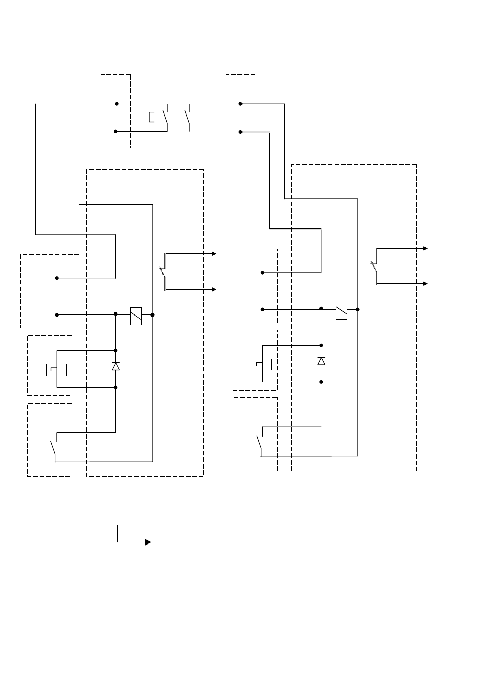
4.3.6 Shunt trip control circuit
-S2
• The closing STOP signal is provided for resetting K2 on the SU-control circuit. It effects with priority in switching
OFF (by ST or UVR) before switching ON. Once switching ON and OFF signals are simultaneous, switching OFF
command will stay longer, than switching ON. It means, that OFF command is a master command.
• The coils energize for short time only. After main contacts opening, switch HS 11 and HS12 cuts off both trips.
• Manual closing of the breaker, while –S2 contact is closed, leads to overheating of ST coils and its damage.
Fig. 21 Shunt trips control circuit
-K1
-X113: ST PCB
[ 4 ]
[ 3 ]
[ 5 ]
[ 8 ]
[ 6]
[ 7 ]
[ 10 ]
[ 9 ]
[ 1 ]
[ 2 ]
-X110/111
](-)
24 V DC
] (+)
[ 7
[ 9
1
ST
ST coil
-K1
Closing
STOP relay
Key position - 5
Key number - 00: Without shunt trips or zero voltage releases.
Key number - 10: With shunt trips.
37/ _ _ _ X _ _ _
-X2
[ 6
[ 7 ]
]
-X2
[ 8 ]
[ 9 ]
Cut-
con
-HS
off
tact
11
-X13: ST PCB
[ 4 ]
[ 3 ]
[ 5 ]
[ 8 ]
[ 6 ]
[ 7 ]
[ 10 ]
[ 9 ]
[ 1 ]
[ 2 ]
-X10/11
[ 7
[ 9
](-)
24 V DC
] (+)
2
ND
ST coil
-K1
Closing
STOP relay
Cut-off
contact
-HS12
-K1
22
Design and specifications are subject to change without notice
DTR01807 rev.02 2010-02-16