1 safety distances and outlined dimensions – GE Industrial Solutions GERAPID 8007R, 10007R WITH ARC CHUTES 1X2, 1X3 User Manual
Page 27
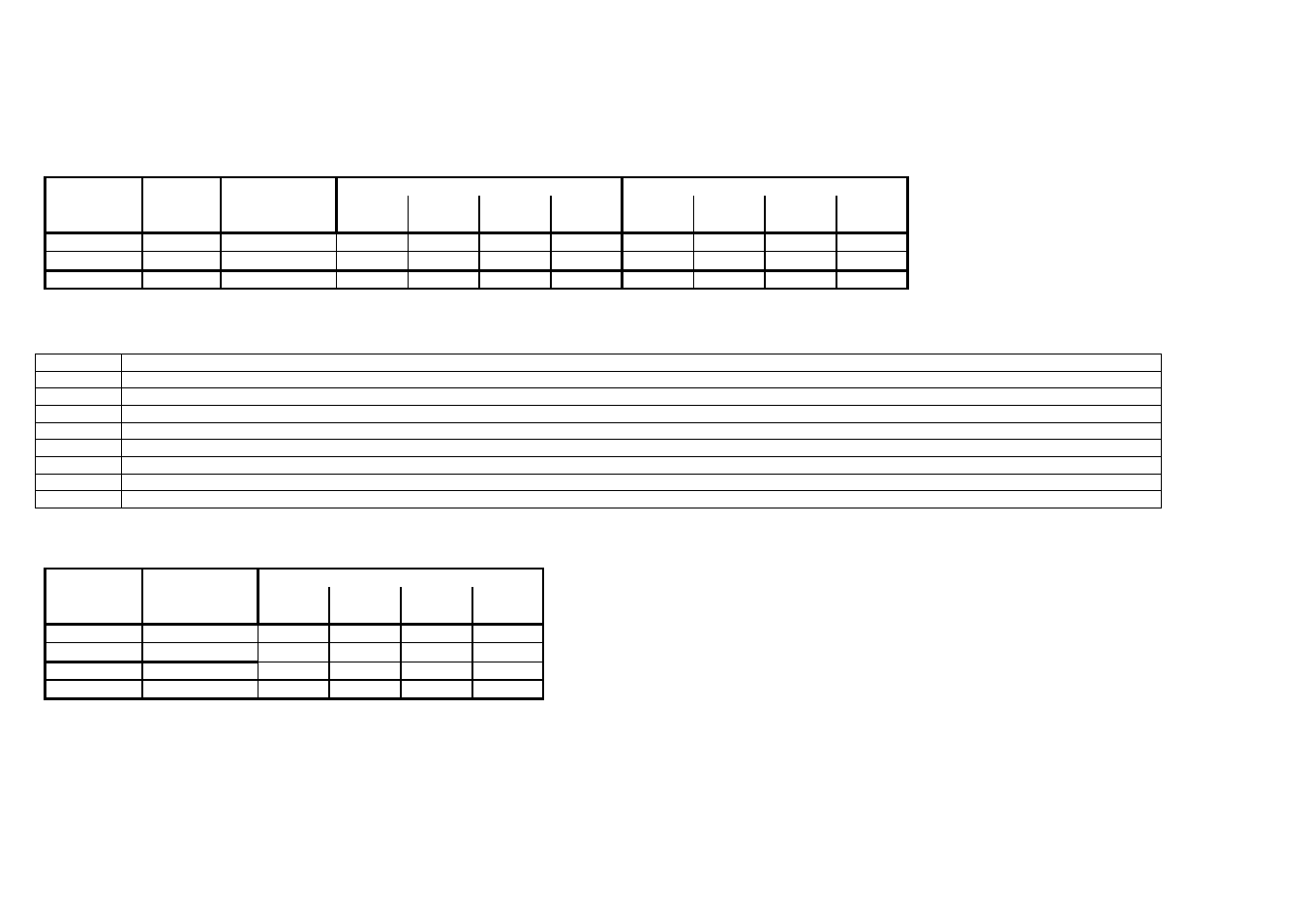
5.1 Safety distances and outlined dimensions.
Units call in mm and inches.
Type
Arc chute
Main-
Gerapid
Connection
A
B
C
D
A
B
C
D
mm/in
mm/in
mm/in
mm/in
mm/in
mm/in
mm/in
mm/in
8007R
1x2
all
600 / 23.6 530 / 20.9 530 / 20.9
190 / 7.5
600 / 23.6 280 / 11.0 280 / 11.0
190 / 7.5
1x3
all
600 / 23.6 530 / 20.9 530 / 20.9
190 / 7.5
600 / 23.6 280 / 11.0 280 / 11.0
190 / 7.5
10007R
1x2
all
600 / 23.6 530 / 20.9 530 / 20.9
190 / 7.5
600 / 23.6 280 / 11.0 280 / 11.0
190 / 7.5
Cubicle with blank grounded walls
Cubicle with insulated walls
Legend for dimensional drawing
K
Additional heat sinks for Gerapid 10007R
L
All openings respectively free areas on the top of the cubical shall be not less than 50%
M
Solenoid closing drive
P
Diameter 9 mm [0,35 in], Countersunk screw M8
S
Control box
Z
Main connectors
*)
Dimensions valid only for Gerapid 8007R version.
**)
Dimensions valid only for Gerapid 10007R version.
***)
Lifting eye fi 25 mm [ ~ 1 in]
Main terminals dimensions:
Type
Connection
Gerapid
version
A
B
C
D
mm/in
mm/in
mm/in
mm/in
8007R
R01
74 / 2.91
23 / 0.91
22 / 0.87
22 / 0.87
R02
50 / 1.97
41 / 1.61
27 / 1.06
36 / 1.42
10007R
R01
74 / 2.91
23 / 0.91
22 / 0.87
22 / 0.87
R02
50 / 1.97
41 / 1.61
27 / 1.06
36 / 1.42
Dimensions on the drawing
2010-02-16 DTR01807 rev.02
Design and specifications are subject to change without notice
27