4 neko control circuits, 37/ _ x, X16: neko pcb – GE Industrial Solutions GERAPID 8007R, 10007R WITH ARC CHUTES 1X2, 1X3 User Manual
Page 18
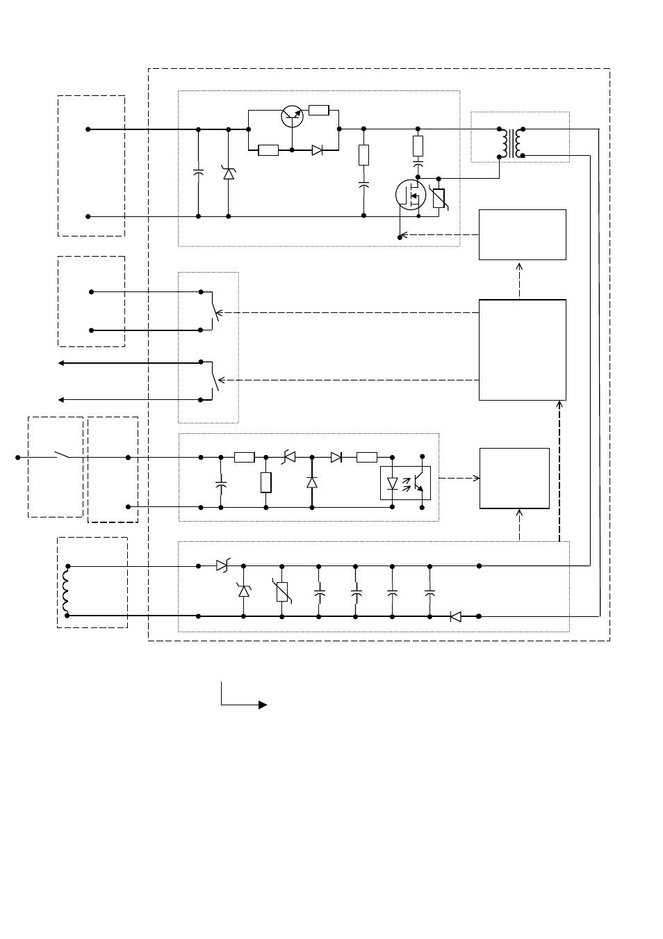
4.3.4 NEKO control circuits
• Firing signal at (-X2 :10/:11) is processed by opto-coupler. Pay attention to the polarity!
• Closing STOP signal is provided to lock CLOSE command, until capacitors are fully charged.
• Be sure that voltage level is between DC 6 V - 24 V and there are no transient spikes (<3 ms) on firing signal.
This can lead to major defect of the NEKO control unit!
•
Maximum duration of the firing command must not exceed ~1 sec. Longer signal might cause NEKO failure! It is
recommended to use one of HS auxiliary contacts connected in series with firing circuit (-X2 :10). It will
automatically cut off the firing circuit after breaker opening.
Fig. 19a 1
st
impulse release system with ED coil and internal NEKO control unit
Cut-off
contact
i.e. HS 9
Provided
by user!
Key position - 3
Key number - 2: With ED coil and internal NEKO control unit.
37/ _ X _ _ _ _ _
-X10/11
[ 8 ]
(+)
24 Vdc
[ 6 ]
(-)
-X3
[ 6 ]
C-bank
charging
signalization
[ 7 ]
-Q2
ED impulse
coil no.1
-X16: NEKO PCB
[ 1 ]
(+)
(-)
[ 2 ]
[ 9 ]
[ 10 ]
[ 5 ]
[ 6 ]
[ 3 ]
(+)
(-)
[ 4 ]
[ 11]
[ 12 ]
Isolating Transformer
-X2
[ 10 ]
Tripping
signal
6V...24V
[ 11 ]
Impulse switching
Charging Control
Charging Voltage
Control
Signals
-K1
-K2
Closing
STOP relay
Input circuit for firing signal
Firing signal
control
C-bank and output circuit
18
Design and specifications are subject to change without notice
DTR01807 rev.02 2010-02-16