4 polarized over current release (code 7), Fig. 5 tripping yoke of the poct release, 5 ed impulse coil release (code 12) – GE Industrial Solutions GERAPID 8007R, 10007R WITH ARC CHUTES 1X2, 1X3 User Manual
Page 7: 6 auxiliary tripping devices (code 11), 7 forced tripping release (code 13)
3.2.4 Polarized over current release (Code 7)
•
The POCT release is a magnet with two magnetic circuits.
The first one (tripping yoke) provides bi-directional
tripping function. The second one (blocking yoke) provides
unidirectional blocking function.
•
This technology ensures fast tripping in reverse current
direction and no tripping in case of forward current. This
system does not require an auxiliary control voltage or
protection relay to operate. It is a direct acting and
instantaneous tripping device.
•
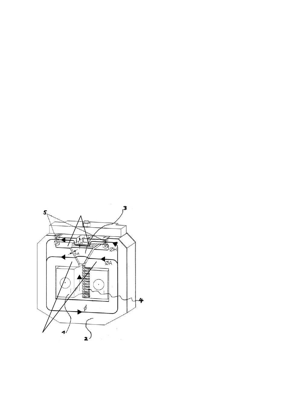
The tripping yoke [Fig. 7] consists of the holding circuit [6],
the movable armature [3] and the tripping circuit [7]. The
holding and the tripping magnetic circuits are both
excited by load current [1]. Until the static overload
release’s response threshold has been reached, the
armature [3] is held in position by the holding flux (ΦH) [2]
and the counter spring’s force [4]. Once the load current
exceeds the set static response threshold, the attraction
flux (ΦA) [2] takes over and rapidly pulls down the flexible
armature [3]. During this operation, the armature hits the
seesaw, which releases the quick latch in the mechanism.
The latch and contacts are opened immediately.
•
The response threshold can be easily adjusted by turning
the adjustment nut with a SW6 hexagon wrench. The
available ranges are described below. Other ranges might
be possible on request.
•
The blocking system of POCT consists of main magnet
circuit, permanent magnet oscillator and blockades. If the
main current in forward direction exceeds 250A, the
locking system starts to operate and counteracts tripping.
This makes the breaker a unidirectional device.
•
Following tripping ranges are available: 0.4-1.2 kA; 0.8-
2.5 kA; 2.0-6.0 kA; 4.0-8.0 kA.
Fig. 5 Tripping yoke of the POCT release.
3.2.5 ED impulse coil release (Code 12)
•
To detect high short circuit currents early and to record
leakage currents in long peripheral sections (for railway
equipment), whose final values are lower than the highest
operating currents, protective relays for monitoring a
current increase should be utilized. If a fault occurs, a
release signal can be passed on to the ED impulse coil
and capacitor release (NEKO), which causes the breaker
to open rapidly (opening delay <3ms).
•
This tripping device can be ordered as an accessory for
the breaker, either alternatively, or additionally to a shunt
trip or a zero voltage release.
•
ED impulse release requires an external protective relay
for monitoring a current increase. This relay must be
provided and installed by the customer.
•
Customer supplied capacitor trip unit may be used. Rated
voltage of 300 V and capacity of 2 000 µF per coil is
required. Rectifier breakers utilize two ED coils.
•
WARNING: ED Firing signal voltage level is between 6 V
and 24 V. There should be no spikes on the signal of
duration less 3 ms. This can lead to failure of the NEKO
board!
•
WARNING: Maximum duration of the firing signal must
not exceed ~1 sec. Longer signal can lead to NEKO
overheating! It is recommended to use an auxiliary
contact in serial connection with firing circuits. It will
automatically cut off the firing circuits after opening.
3.2.6 Auxiliary tripping devices (Code 11)
•
The breaker can be equipped with either a shunt trip (ST,
a-release) or a zero voltage release (UVR, r-release).
•
Both trips work at a voltage level of 24VDC. A voltage
transformer, which is integrated into the breaker, adapts
to other voltage levels and provides the energy required
by the breaker mechanism (except for the drive).
6
•
Optionally, it’s possible to supply both devices directly to
external 24 V DC ( ± 5%). In this case the release signal for
ST shall not be longer 100 ms.
•
The shunt trip is used for remote actuation. It is designed
for intermittent operation (ED=9%) and is always
connected through an auxiliary contact to ensure that is
only energized during the time until the breaker is
opened.
7
•
The UVR’s winding is designed for continuous operation.
In case of a control voltage drop, the release mechanism
opens the breaker. It is therefore possible to use the
release in combination with the electronic trip unit for
voltage monitoring, i.e. for motor starters, where an
unintended re-start of a motor after a temporary voltage
breakdown is to be prevented. Due to their operational
mode, UVRs are self-monitoring devices, i.e. the breaker is
tripped upon a break of the pilot wire (EMERGENCY-OFF
principle).
•
WARNING: Manual closing of the breaker with shunt trips
installed, while signal OPEN is active and control power is
applied, may lead to shunt coil overheating and damage.
2010-02-16 DTR01807 rev.02
Design and specifications are subject to change without notice
7