7 zero voltage releases control circuit, Fig. 22 zero voltage releases control circuit, 37/ _ _ _ x – GE Industrial Solutions GERAPID 8007R, 10007R WITH ARC CHUTES 1X2, 1X3 User Manual
Page 23: X14: uvr pcb, X114: uvr pcb
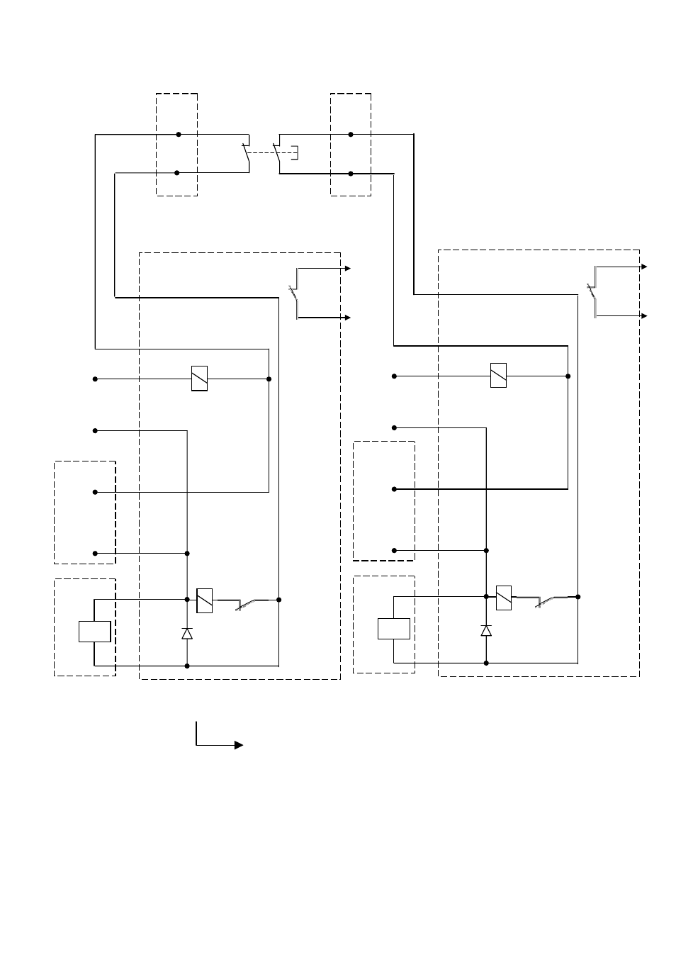
4.3.7 Zero voltage releases control circuit
• The closing STOP signal is provided for resetting K2 on the SU-control circuit. It effects with priority in switching
OFF (by ST or UVR) before switching ON. Once switching ON and OFF signals are simultaneous, switching OFF
command will stay longer than switching ON. It means, that OFF command is master command.
Fig. 22 Zero voltage releases control circuit
Key position - 5
Key number - 00: Without shunt trip or zero voltage releases.
Key number - 20: With zero voltage releases.
37/ _ _ _ X _ _ _
-K1
-K2
X14: UVR PCB
[ 5 ]
[ 1 ]
[ 6 ]
[ 2 ]
[ 3 ]
[ 4 ]
[ 7 ]
[ 8 ]
[ 9 ]
[ 10 ]
-X10/11
[ 7 ](-)
DC 24 V
[ 8 ] (+)
1
st
UVR
coil
U<
-K1
Closing
STOP relay
-S2
-X2
[ 6 ]
[ 7 ]
-X2
[ 8 ]
[ 9 ]
-X114: UVR PCB
[ 5 ]
[ 1 ]
[ 6 ]
[ 2 ]
[ 3 ]
[ 4 ]
[ 7 ]
[ 8 ]
[ 9 ]
[ 10 ]
-X110/
-X111
[ 7 ](-)
DC 24 V
[ 8 ] (+)
2
nd
UVR
coil
U<
-K1
Closing
STOP relay
-K2
-K1
-K2
-K2
2010-02-16 DTR01807 rev.02
Design and specifications are subject to change without notice
23