12 electronic control system, Fig. 13 control box with control pcbs, Fig. 13-1 neko control unit – GE Industrial Solutions GERAPID 8007R, 10007R WITH ARC CHUTES 1X2, 1X3 User Manual
Page 10: Fig. 13-2 voltage converter 110 v/24 v dc, Fig. 13-3 su control unit, Fig. 13-4 uvr control unit, Fig. 13-5 st control unit
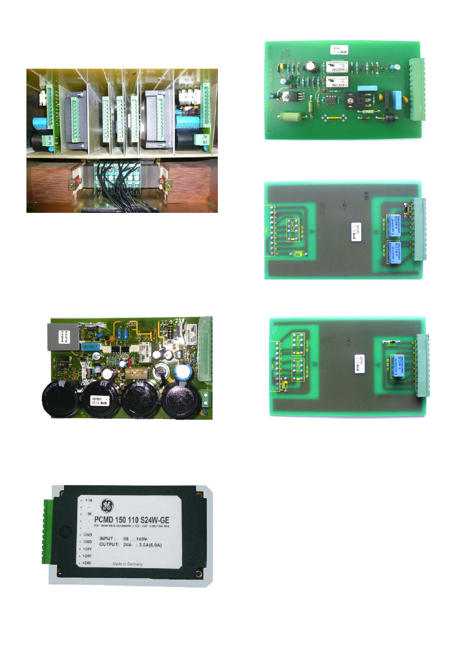
3.2.12 Electronic control system
All the control PCBs are installed in control box [Fig. 13].
Starting from the left, these are:
Fig. 13 Control box with control PCBs.
•
(1) NEKO control unit [Fig. 13-1] (Code 12) – internal
control unit with capacitor bank. Releases firing signal for
ED coil and provides indication of the capacitors charging.
NEKO control unit also blocks the firing signal until C-bank
is fully charged (~15 sec).
•
WARNING: NEKO unit requires a high quality signal. Be
sure, that voltage level is between 6 V…24 V DC and there
are no short spikes on signal (<3 ms). This may lead to
major defect of the NEKO control unit!
Fig. 13-1 NEKO control unit
•
(2) Internal voltage converter (Code 8) - converts
external supply voltage (-X3 :4/:5) to the internal
24 V DC. Required by controls (except for the drive
supply).
Fig. 13-2 Voltage converter 110 V/24 V DC.
•
(3) SU control unit.
1 2 3 4 3 2 1
Fig. 13-3 SU control unit.
•
(4) ST (a- trip) and UVR (r- release) control unit..
Fig. 13-4 UVR control unit
Fig. 13-5 ST control unit
10
Design and specifications are subject to change without notice
DTR01807 rev.02 2010-02-16