Group a group b, Control bus cables routing – GE Industrial Solutions ISM User Manual
Page 19
Modifications reserved
Page 19/34
OPM_ISM_OPT_10K_M50_0GB_V021.doc
Operating Manual ISM – Intelligent Synchronization Module
IS
M_
LB
S
_
C
B
C
c
o
nn
ec
ti
on_03G
B
UPS 3
UPS 2
Q1
Q2
OF
F
ON
ON
OF
F
Q2
OF
F
ON
OF
F
ON
Q1
UPS 1
OF
F
OF
F
Q2
ON
ON
Q1
UPS 1
UPS 3
UPS 2
Q2
Q2
ON
OF
F
ON
Q1
OF
F
Q2
ON
OF
F
Q1
OF
F
ON
OF
F
ON
Q1
OF
F
ON
P5
P6
GROUP A
GROUP B
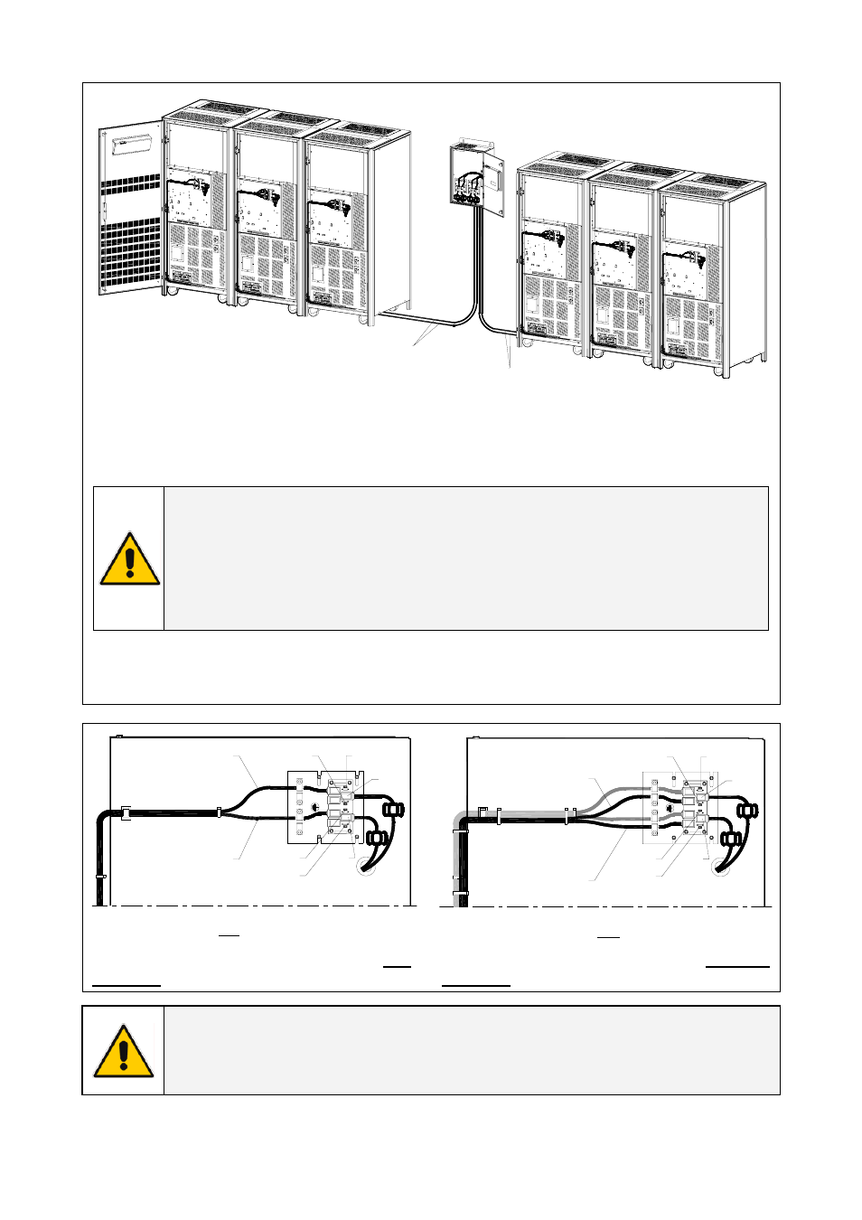
Fig. 4.6-1/2
ISM
From ISM to UPS 1 / Group A
Control bus cables Group A
Control bus cables Group B
(from ISM to UPS 1 / Group B)
See Fig. 4.6-5/6
See Fig. 4.6-5/6
Fig. 4.6-4 Connection of the communication bus cables from ISM to UPS’s Group A and Group B
Control bus cables routing
Place and fix the cables JA and JB with the appropriate clamps inside the UPS cabinets.
Pay attention to the fact, that routing of cables shall allow the removal of the protection covers.
NOTE !
Pay attention when cabling and routing the bus cables JA and JB inside the UPS
cabinet.
In case the unit should be removed from the system, the control bus cables Group A
and Group B must be removed from the cabinet without disconnecting them from
the metal plates where are located the sockets JA and JB. Please contact your
Service Centre.
For reliability reasons the cables JA and JB connecting the units should be run in separated
protected conduits, as well as separated from the power cables.
It is important that the cable JA is as long as cable JB.
ISM_LBS_RPA-IM0048_01
JP3
JP1
JP4
IM 0048
JP2
JP1
JP2
JP4
JP3
JB1
JA1
JB
JA
Fig. 4.6-5 PCB “P34 – Parallel Bus Interface” of UPS number 1 of either
Group A or B, prior to the connection with ISM
JP2
JP1
JP3
JP4
JP3
JP2
JP1
JP4
IM 0048
Control Bus cable from ISM
Control Bus cable from ISM
ISM_LBS_RPA-IM0048_02GB
JA
JB
JB
JA
Fig. 4.6-6 PCB “P34 – Parallel Bus Interface” of UPS number 1 of
either Group A or B, after the connection with ISM
The Jumpers JP1, JP2, JP3 and JP4 ARE
INSERTED.
The Jumpers JP1, JP2, JP3 and JP4 MUST BE
REMOVED.
NOTE !
Since the position of PC Board “P34 – Parallel Bus Interface” inside the UPS changes
between the various UPS output powers, it’s recommended to consult the
appropriate Operating Manual for cable connections.