4 place of installation, Group a group b, The ism should be mounted flush to a wall – GE Industrial Solutions ISM User Manual
Page 14
Modifications reserved
Page 14/34
OPM_ISM_OPT_10K_M50_0GB_V021.doc
Operating Manual ISM – Intelligent Synchronization Module
4.4 PLACE
OF
INSTALLATION
The ISM should be installed in a restricted area where only qualified personnel should be admitted.
The place of installation should be clean, dust-free, and provided with proper ventilation or air-
conditioning.
We strongly advice that the ambient temperature should not exceed 20° to 25°C / 68° to 77°F (max.
35°C / 95°F).
NOTE !
The installation of the ISM must be executed by QUALIFIED PERSONNEL ONLY.
A single-phase power outlet should be provided near the ISM for connection of power tools or test
equipment. This outlet must be grounded.
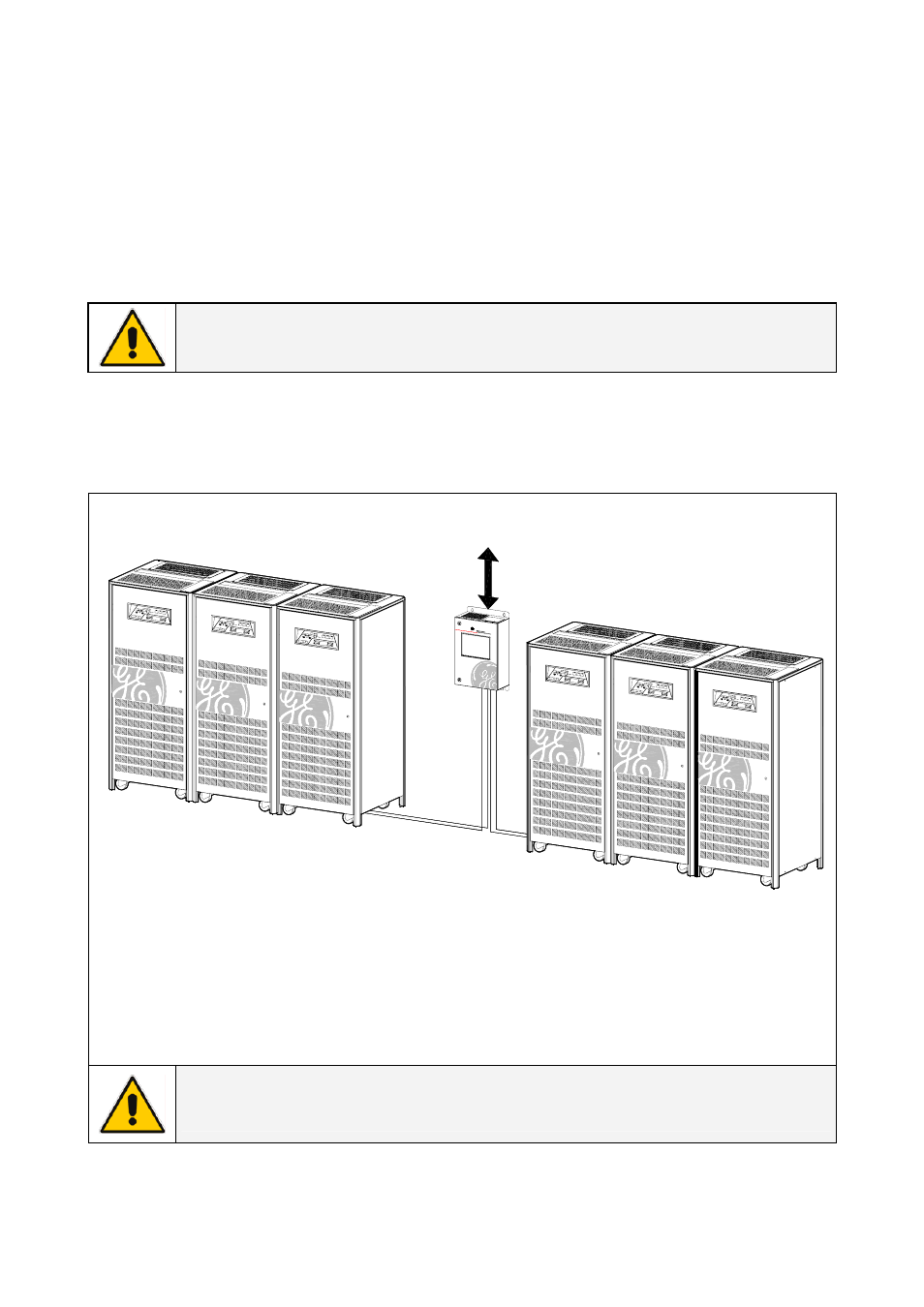
ISM positioning
IS
M
_LBS_C
abinet
dis
p
o
s
it
ion_0
1GB
UPS 3
UPS 2
UPS 1
UPS 1
UPS 2
UPS 3
GROUP A
GROUP B
IS
M
_
C
a
b
in
e
t_
G
E
_
0
3
TM
400mm / 16"
Min.
Fig. 4.4-1 ISM positioning
The ISM should be mounted flush to a wall.
Clearance around the front of the ISM should be sufficient to enable free passage of personnel with
the door fully open, and to allow sufficient airflow for the ventilation.
Recommended minimum clearance between the ceiling and the top of the ISM should be 400 mm
(16 “) for proper cooling air exhaust.
NOTE !
The bolts used for fixing the ISM to the wall must be adequate for its weight.