6 control bus cables connection, Maximal number of upss in one group is 6 – GE Industrial Solutions ISM User Manual
Page 18
Modifications reserved
Page 18/34
OPM_ISM_OPT_10K_M50_0GB_V021.doc
Operating Manual ISM – Intelligent Synchronization Module
4.6 CONTROL BUS CABLES CONNECTION
WARNING !
The installation and connection must be performed by QUALIFIED SERVICE
PERSONNEL only.
Refer to the “Safety prescriptions - Installation” described on page 6.
Carefully read the following recommendations before proceeding:
•
Ensure that the AC external isolators are Off, and prevent their in adverted operation.
•
Do not close any external isolators prior to the commissioning of the equipment.
•
The input / output cables must be put in order and fixed, taking care to avoid risk of short-circuit
between different poles.
•
The earthing connection of the electrical system must be in accordance with local regulations.
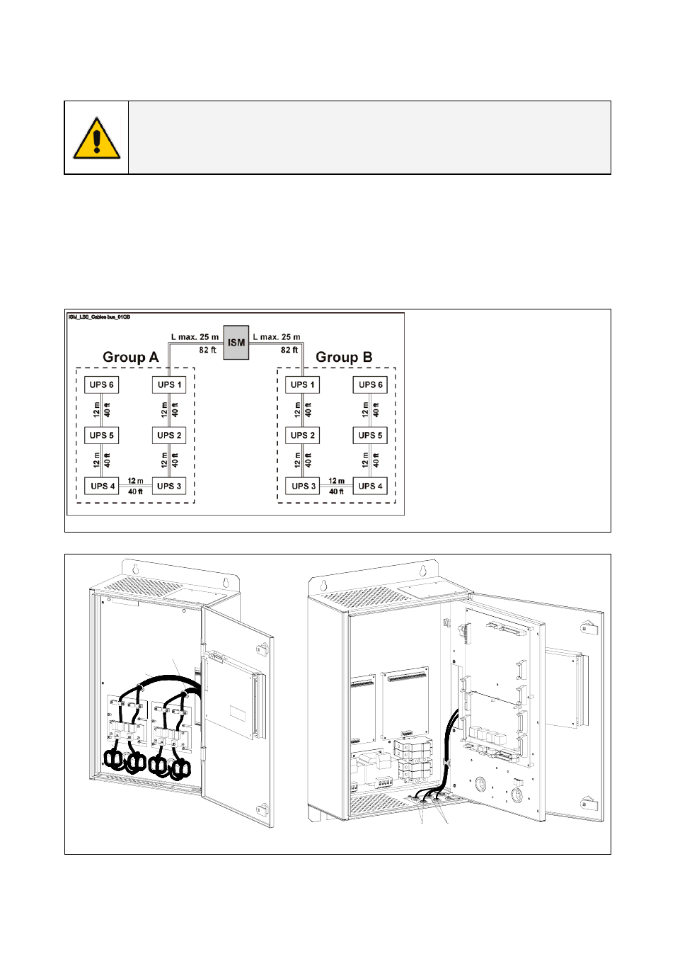
Fig. 4.6-1 Diagram showing the maximum allowable length of communication cables
The standard length of the control
bus cable between ISM and the
first unit of each group is 12 m / 40
ft.
Maximum distance between ISM
and the last unit of each group is
85 m / 279 ft.
L max. :
85 m – [(No. of UPS – 1) x 12 m]
279 ft – [(No. of UPS – 1) x 40 ft]
Maximal number of UPSs in one
group is 6.
ISM_L
B
S_C
B
C
c
onnec
ti
on_01G
B
P6
P5
J52
J53
J63
J62
JA
2
JA
1
JB
2
JB
1
JB
1
JB
2
JA
1
JA
2
Control bus cables
Group A
Control bus cables
Group B
Fig. 4.6-2 Connection of the cables of the communication
bus to P5 / P6 – Parallel bus interface
Control bus cables
Group B
Control bus cables
Group A
IS
M
_
L
BS_
CBC
c
onnec
tion
_02GB
Fig. 4.6-3 Internal connection of the communication bus cables