L1 l2 pe pe l3 l1 gr oup a grou p b, Fuses rating, For 208 vac – GE Industrial Solutions ISM User Manual
Page 17: Connection of power supply input cables
Modifications reserved
Page 17/34
OPM_ISM_OPT_10K_M50_0GB_V021.doc
Operating Manual ISM – Intelligent Synchronization Module
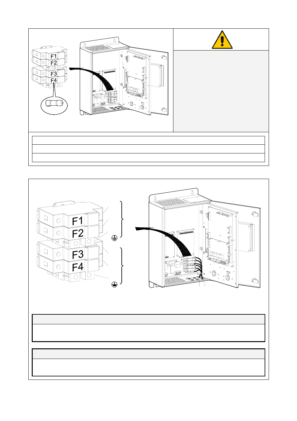
Fuses rating
IS
M_
L
BS_
F
1
-2
-3
-4
_
0
1
F1-F2-F3-F4
Fig. 4.5-4 Fuses rating
NOTE !
Verify for correct fuse rating “F1 - F2
- F3 - F4” on dependence of the
power supply input voltage,
according to the table below.
In case of replacement the same
type and the same rating must be
used.
The replacement of fuses must be
performed by QUALIFIED SERVICE
PERSONNEL only.
For 208 VAC
0.75 A
Fuse type Class CC – Time Delay – 13/32” x 1 1/2” – 600 VAC
For 400 VAC
0.3 A
Fuse type Class CC – Time Delay – 13/32” x 1 1/2” – 600 VAC
For 480 VAC
0.3 A
Fuse type Class CC – Time Delay – 13/32” x 1 1/2” – 600 VAC
Connection of power supply input cables
IS
M
_
LB
S
_
Co
nn
ec
ti
o
n
p
o
w
er
_
0
1
L1
L2
PE
PE
L3
L1
GR
OUP A
GROU
P B
Group A
Group B
Fig. 4.5-4 Connection of power supply input cables
Input glands are suitable for cables having diameters: from 6 mm to 12 mm / 2.37” to 4.73”
ISM Input A
L1
Phase L1 from Output Load Group A
PE Ground from Output Load Group A
L2
Phase L2 from Output Load Group A
ISM Input B
L1
Phase L1 from Output Load Group B
PE Ground from Output Load Group B
L3
Phase L3 from Output Load Group B