5 control panel, 1 control panel, Sync auto – GE Industrial Solutions ISM User Manual
Page 21: Off sync, Alarm, Service
Modifications reserved
Page 21/34
OPM_ISM_OPT_10K_M50_0GB_V021.doc
Operating Manual ISM – Intelligent Synchronization Module
5 CONTROL
PANEL
5.1 CONTROL
PANEL
MAINTENANCE
MAINTENANCE
SYNC
ALARM
SERVICE
MUTE
LOAD
BYPASS
INVERTER
BYPASS
INVERTER
GROUP B
GROUP A
BYPASS OK
INVERTER OK
B SYNC TO A
A SYNC TO B
INVERTER OK
BYPASS OK
STS
SYNC MASTER
A
B
METERING
ALARMS
PARAMETERS
+
-
ENTER
AUTO
SYNC
OFF
ISM_LBS_Control panel_01
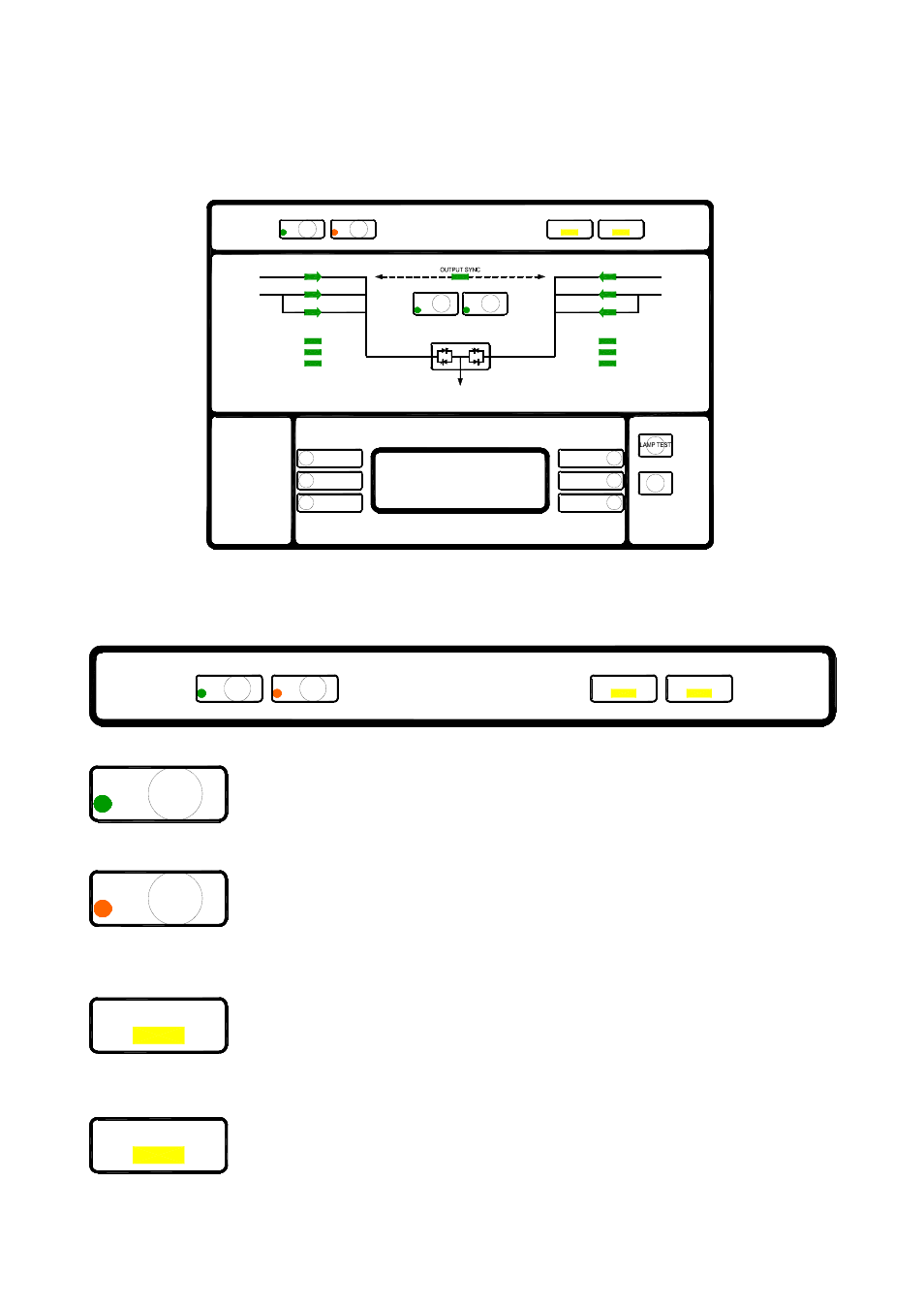
Fig. 5.1-1 General Control Panel
5.2 TABLE OF FUNCTIONS AND INDICATIONS ON CONTROL PANEL
SYNC
ALARM
SERVICE
AUTO
SYNC
OFF
ISM_LBS_CP 1_01
Fig. 5.2-1 Control Panel – Part 1
SYNC
AUTO
SYNC AUTO – Green LED
When lit, it indicates that the sync command is active and that the inverters of
Group A and B will be synchronized to the selected “Super Master”.
The “Super Master” will be automatically chosen.
OFF
SYNC
SYNC OFF – Red LED
When lit, it indicates that the sync command is disabled due to one or both of the
following conditions:
• SYNC command is OFF;
• One of the two (2) UPS groups is not present.
ALARM
ALARM – Yellow LED
General alarm condition.
It blinks when one or more alarm is activated. The internal buzzer is ON.
The LED remains lighted (with alarm condition still present) and the buzzer stops
as the key “mute” has been pressed.
SERVICE
SERVICE – Yellow LED
When lit it indicates that a regular maintenance service is needed.
May be reset by a service technician only. See Section 8 – Maintenance.