5 electrical wiring – GE Industrial Solutions ISM User Manual
Page 15
Modifications reserved
Page 15/34
OPM_ISM_OPT_10K_M50_0GB_V021.doc
Operating Manual ISM – Intelligent Synchronization Module
4.5 ELECTRICAL
WIRING
WARNING !
The installation and connection must be performed by QUALIFIED SERVICE
PERSONNEL only.
Refer to the “Safety prescriptions - Installation” described on page 6.
Carefully read the following recommendations before proceeding:
•
Ensure that the AC external isolators are Off, and prevent their inadvertent operation.
•
Do not close any external isolators prior the commissioning of the equipment.
•
The input / output cables must be put in order and fixed, taking care to avoid risk of short-circuit
between different poles.
•
The earthing connection of the electrical system must be in accordance with local regulation.
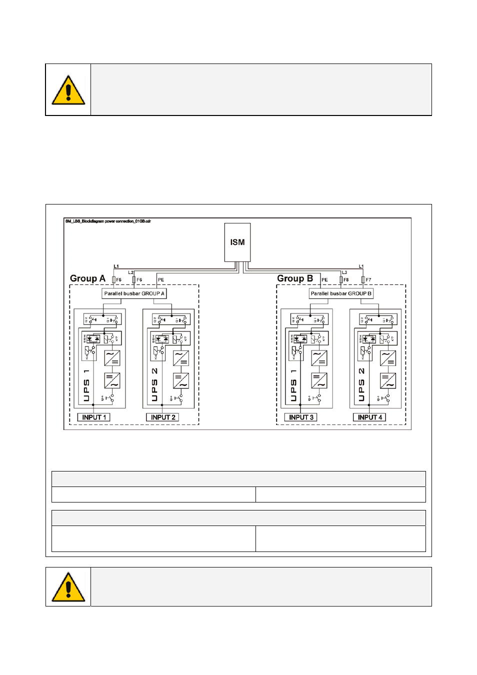
Input overcurrent protection and wire sizing
Fig. 4.5-1 Input overcurrent protection and wire sizing
For correct rating of fuses and cable sections for input power of the ISM see data indicated in the
tables below.
Fuses AgL or Circuit breakers
Group A: F5 – F6 & Group B: F7 – F8
2 x (2 x 2 A)
Wire sizing
Group A: L1 + L2 + PE & Group B: L1 + L3 + PE
Min. 3 x 1.5 mm
2
/ Max. 3 x 2.5 mm
2
Min. 3 x 16 AWG / Max. 3 x 14 AWG
NOTE !
The delivery and installation of fuses and input connections of the ISM are at the
customer’s expense, unless agreed otherwise.