Car2012te series rectifier, Data sheet – GE Industrial Solutions CAR2012TE series User Manual
Page 9
GE
Data Sheet
CAR2012TE series rectifier
Input: 85Vac to 264Vac; Output: 12 Vdc @ 2000W; 3.3Vdc or 5 Vdc @ 4A
February 9, 2014
©2013 General Electric Company. All rights reserved.
Page 9
and alarm registers get reset into their alarm state, however,
the SMBAlert# does not assert again.
‘Manufacturer Specific’ commands are used to support
instructions that are not offered by the PMBus™ specification.
All communication over the PMBus interface must support
Packet Error Checking (PEC). The PMBus master must
generate the correct PEC byte for all transactions, and check
the PEC byte returned by the power supply.
Non-volatile memory is used to store configuration settings.
Not all settings programmed into the device are
automatically saved into this non-volatile memory. Only those
specifically identified as capable of being stored can be
saved. (see the Table of Commands for which command
parameters can be saved to non-volatile storage).
Default state:
Power supplies are programmed in the default
state to automatically restart after a shutdown has occurred
for over current and over temperature. The default state can
be reconfigured by changing non-volatile memory
(Store_default_code).
Re-initialization:
The I
2
C code is programmed to re-initialize if
no activity is detected on the bus for 5 seconds. Re-
initialization is designed to guarantee that the I
2
C µController
does not hang up the bus. Although this rate is longer than
the timing requirements specified in the SMBus specification,
it had to be extended in order to ensure that a re-initialization
would not occur under normal transmission rates. During the
few µseconds required to accomplish re-initialization the I
2
C
µController may not recognize a command sent to it. (i.e. a
start condition).
Read back delay:
The power supply issues the SMBAlert #
notification as soon as the first state change occurred.
During
an event a number of different states can be transitioned to
before the final event occurs. If a read back is implemented
rapidly by the host a successive SMBAlert# could be triggered
by the transitioning state of the power supply. In order to
avoid successive SMBAlert# s and read back and also to
avoid reading a transitioning state, it is prudent to wait more
than 2 seconds after the receipt of an SMBAlert# before
executing a read back. This delay will ensure that only the
final state of the power supply is captured.
Successive read backs:
Successive read backs to the power
supply should not be attempted at intervals faster than every
one second. This time interval is sufficient for the internal
processors to update their data base so that successive
reads provide fresh data.
Non-supported commands:
Non supported commands are
flagged by setting the appropriate STATUS bit and issuing an
SMBAlert# to the ‘host’ controller. If a non-supported read is
requested the power supply will return 0x00h for data.
Data out-of-range:
The power supply validates data settings
and sets the data out-of-range bit and SMBAlert# if the data
is not within acceptable range.
Master/Slave:
The ‘host controller’ is always the MASTER.
Power supplies are always SLAVES. SLAVES cannot initiate
communications or toggle the Clock. SLAVES also must
respond expeditiously at the command of the MASTER as
required by the clock pulses generated by the MASTER.
Clock stretching:
The ‘slave’ µController inside the power
supply may initiate clock stretching if it is busy and it desires
to delay the initiation of any further communications. During
the clock stretch the ‘slave’ may keep the clock LO until it is
ready to receive further instructions from the host controller.
The maximum clock stretch interval is 25ms.
The host controller needs to recognize this clock stretching,
and refrain from issuing the next clock signal, until the clock
line is released, or it needs to delay the next clock pulse
beyond the clock stretch interval of the power supply.
Note that clock stretching can only be performed after
completion of transmission of the 9
th
ACK bit, the exception
being the START command.
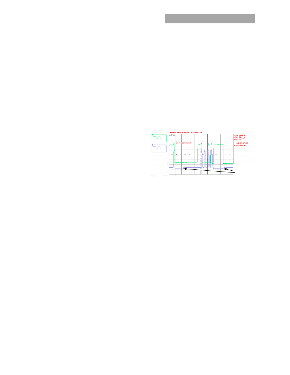
Figure 1. Example waveforms showing clock stretching.
I
²C Bus Lock-Up detection:
The device will abort any
transaction and drop off the bus if it detects the bus being
held low for more than 35ms.
Communications speed:
Both 100kHz and 400kHz clock
rates are supported. The power supplies default to the
100kHz clock rate. The minimum clock speed specified by
SMBus is 10 kHz.
Packet Error Checking (PEC):
The power supply will not
respond to commands without the trailing PEC because the
integrity of communications is compromised without packet
error correction deployment.
PEC is a CRC-8 error-checking byte, based on the polynomial
C(x) = x
8
+ x
2
+ x + 1, in compliance with PMBus™
requirements. The calculation is performed on all message
bytes, including the originating write address and command
bytes preceding read instructions. The PEC is appended to the
message by the device that supplied the last byte.
SMBAlert#
:
The µC driven SMBAlert# signal informs the
‘master/host’ controller that either a STATE or ALARM change
has occurred. Normally this signal is HI. The signal will change
to its LO level if the power supply has changed states and the
signal will be latched LO until the power supply receives a
‘clear’ instruction as outlined below. If the alarm state is still
present after the ‘clear_faults’ command has been received,
then the signal will revert back into its LO state again and will
latch until a subsequent ‘clear_faults’ signal is received from
the host controller.
Clock
Stretch