Car2012te series rectifier, Data sheet, Fault management – GE Industrial Solutions CAR2012TE series User Manual
Page 16: State change definition, Hot plug procedures
GE
Data Sheet
CAR2012TE series rectifier
Input: 85Vac to 264Vac; Output: 12 Vdc @ 2000W; 3.3Vdc or 5 Vdc @ 4A
February 9, 2014
©2013 General Electric Company. All rights reserved.
Page 16
EEPROM record (0xD9):
64 bytes
of EEPROM memory is
available for customer records such as an additional FRU_ID.
Block write is utilized since more than 2 data bytes are
feasible. The first byte will be written into the pointed to
memory location and each subsequent byte is incremented
by a single memory location.
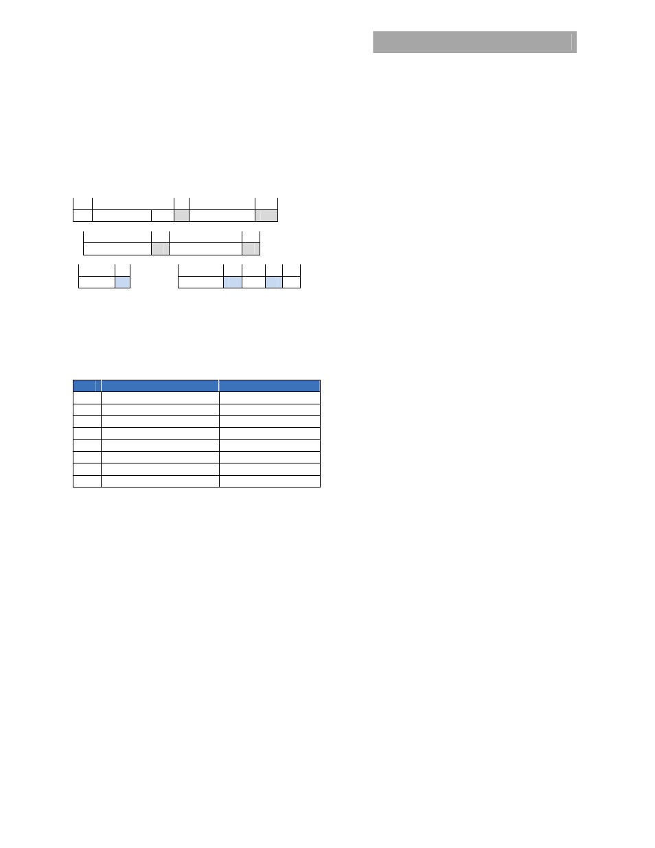
The standard protocol to access these records takes the form;
1 8 1
8
1
S Slave
address Wr A Command
0xD9 A
8 1 8 1
Memory location A Byte
count
≤ 32
A
8 1
8 1
8
1
1
Byte 1
A ………………….. Byte
≤ 32
A PEC A P
The highest memory location is address
0x64b
.
Test Function (0xDF):
This command can be used to exercise
the LEDs of the power supply or the output Or’ing feature of
the power supply.
Bit
Function
State
0
LED test
1:ON, 0:OFF
1 reserved
2 reserved
3 reserved
4
Or’ing test
1:execute, 0:idle
5 reserved
6 reserved
7 reserved
Setting bit 0 of the data byte to 1 instructs the power supply
to execute an LED test. During this test both LEDs are turned
ON and OFF every 0.5 second. The tri-state LED should be
exercised sequentially in its green, orange, and red state. The
test should continue until bit 0 of the data byte is set to 0 in a
subsequent instruction.
Setting bit 5 of the data byte to 1 instructs the power supply
to execute once an output Or’ing test in applications where
multiple paralleled power supplies are utilized. The host
should verify that N+1 redundancy is established. If N+1
redundancy is not established the test can fail. Only one
power supply should be tested at a time.
Verifying test completion should be delayed for
approximately 30 seconds to allow the power supply
sufficient time to properly execute the test.
During the test the power supply will lower its output voltage
and measure the difference between the internal and
external sides of the Or’ing function. This measurement will
determine whether the Or’ing function is working properly.
The system controller must conclude that sufficient power
capacity exists to deliver output power to the system while
this unit is purposely taken off the bus by lowering its output
voltage. Since validity of the test is system control dependent,
the power supply does not conclude whether it is properly
functioning. The system controller must determine whether
the function is working properly.
Valid data bytes are: 0x00, 0x01,0x10,0x11
Fault management
The power supply recognizes that certain transitionary states
can occur before a final state is reached. The STATUS and
ALARM registers will not be frozen into a notification state
until the final state is reached. Once a final state is reached
the SMBAlert# signal is set and the STATUS and ALARM
registers will not get reinstated until a clear_faults is issued by
the master. The only exception is that additional state
changes may be added to the original list if further changes
are noted.
The power supply differentiates between internal faults that
are within the power supply and external faults that the
power supply protects itself from, such as overload or input
voltage out of limits. The FAULT LED, FAULT PIN or i2c alarm is
not asserted for EXTERNAL FAULTS. Every attempt is made to
annunciate External Faults. Some of these annunciations can
be observed by looking at the input LEDs. These fault
categorizations are predictive in nature and therefore there is
a likelihood that a categorization may not have been made
correctly.
Input voltage out of range:
The Input LED will continue
blinking as long as sufficient power is available to power the
LED. If the input voltage is completely gone the Input LED is
OFF.
State change definition
A state_change is an indication that an event has occurred
that the MASTER should be aware of. The following events
shall trigger a state_change;
Initial power-up of the system when AC gets turned ON .
This is the indication from the power supply that it has
been turned ON.
Whenever the power supply gets hot-plugged into a
working system. This is the indicator to the system
(MASTER) that a new power supply is on line.
Any changes in the bit patterns of the STATUS and
ALARM registers are a STATUS change which triggers the
SMBALERT# flag.
Note that a host-issued command such as turning the output
OFF will not trigger an SMBAlert# even though the STATUS
registers will change to indicate the latest state of the power
supply.
Hot plug procedures
Careful system control is recommended when hot plugging a
power supply into a live system. It takes about 15 seconds for
a power supply to configure its address on the bus based on
the analog voltage levels present on the backplane. If
communications are not stopped during this interval, multiple
power supplies may respond to specific instructions because
the address of the hot plugged power supply always defaults