Car2012te series rectifier, Data sheet, Failure predictions – GE Industrial Solutions CAR2012TE series User Manual
Page 17: Leds, Alarm table
GE
Data Sheet
CAR2012TE series rectifier
Input: 85Vac to 264Vac; Output: 12 Vdc @ 2000W; 3.3Vdc or 5 Vdc @ 4A
February 9, 2014
©2013 General Electric Company. All rights reserved.
Page 17
to xxxx000 (depending on which device is being addressed
within the power supply) until the power supply configures its
address.
The recommended procedure for hot plug is the following:
The system controller should poll the module_present signal
to verify when a power supply is inserted into the system.
When a new module is detected the system controller should
cease any communications with the power system for 15
seconds. At the end of the time out all communications can
resume. Note that although hot-plug should not affect
ongoing communications, if a discrepancy should arise the
error should get picked up by the PEC calculation. Ofcourse
the system controller could always use the module_present
signal as an indicator to ignore communications that are
currently taking place.
Failure predictions
Alarm warnings that do not cause a shutdown are indicators
of potential future failures of the power supply. For example,
if a thermal sensor failed, a warning is issued but an
immediate shutdown of the power supply is not warranted.
Another example of potential predictive failure mechanisms
can be derived from information such as fan speed when
multiple fans are used in the same power supply. If the speed
of the fans varies by more than 20% from each other, this is
an indication of an impending fan wear out.
The goal is to identify problems early before a protective
shutdown would occur that would take the power supply out
of service.
Information only alarms:
The following alarms are for
information only, they do not cause a shutdown
Over temperature warning
V
out
out-of-limits (above 36Vdc)
Output voltage lower than bus
Unit in Power Limit
Thermal sensor failed
Or’ing (Isolation) test failure
Power delivery
Stby out of limits
Communication errors
LEDs
Two LEDs are located on the front faceplate. The AC_OK LED
provides visual indication of the INPUT signal function. When
the LED is ON GREEN the power supply input is within normal
design limits.
The second LED DC/FLT is a dual-state LED. When GREEN
there are no faults and DC output is present. When ‘blinking’
a fault condition exists but the power supply may still provide
some output power. When RED , a fault condition exists and
the power supply has been shut down, it does not provide
any output power.
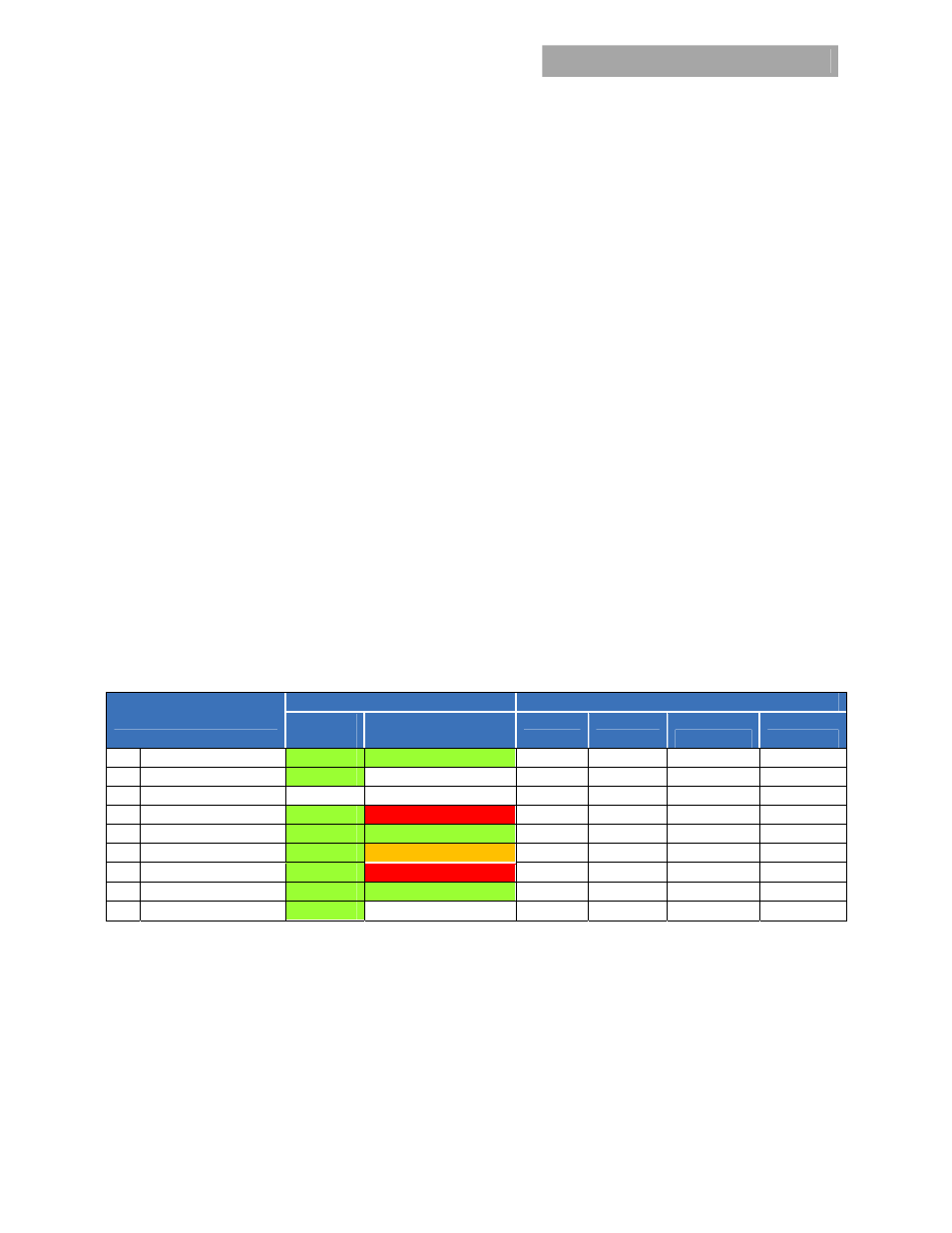
Alarm Table
Test Condition
LED Indicator
Monitoring Signals
LED1
INPUT OK
Tri-Color LED2
Temp OK/DC OK / Fault
FAULT
DC OK
INPUT OK
TEMP OK
1 Normal
Operation
Green
Green
High High High High
2
Out of range INPUT
Blinking
? High
?
Pulsing
High
3 No
Input
OFF
OFF
High
Low
Low
High
4 OVP
Green
Red
Low Low High High
5 Over
Current
Green
Blinking
High Low High High
6
Over Temp Warning
Green
Blinking Orange
High
High High Pulsing
7
Over Temp Fault
Green
Red
Low Low High Low
8 Remote
ON
Green
Green
High High High High
9 Remote
OFF
Green
OFF High
Low
High
High
Notes: Test condition #2 and #3 had 2 modules plug in. One module is running and the other one is with no/low AC.
Test condition #5, The DC_OK signal responds to two independent conditions. It can activate either for loss of output because of an overload
condition, or it can activate because of the impending loss of output voltage because input power has been interrupted. In case of an
overload condition, depending on how deep is the overload, sufficient holdup may not be present to provide the required delay prior to the
regulation going below 10.8 V
DC
.
Blinking of the overload LED will not occur until the output voltage decayed about 0.3V from its regulation point. During hiccup, blinking
occurs only during the ON-time state.
? – module output could be either ON or OFF dependent on output loading and internal capability.
Blinking frequency: 0.5 seconds ON, 0.5 seconds OFF.