Car2012te series rectifier, Data sheet, Pmbus – GE Industrial Solutions CAR2012TE series User Manual
Page 11: Command set, Command descriptions, Standard features
GE
Data Sheet
CAR2012TE series rectifier
Input: 85Vac to 264Vac; Output: 12 Vdc @ 2000W; 3.3Vdc or 5 Vdc @ 4A
February 9, 2014
©2013 General Electric Company. All rights reserved.
Page 11
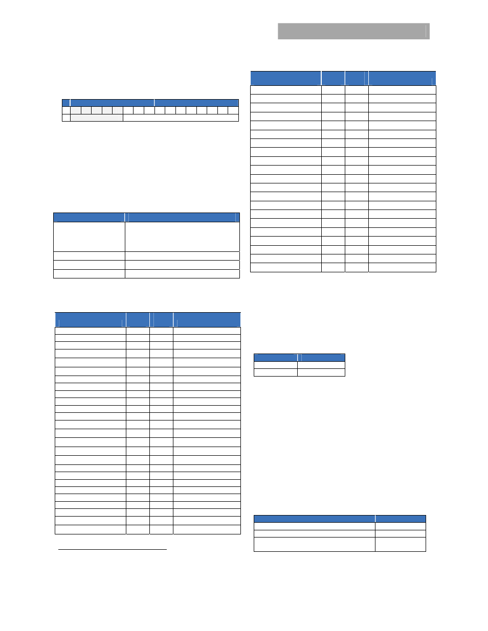
The Linear Data Format is a two byte value with an 11-bit,
two’s complement mantissa and a 5-bit, two’s complement
exponent or scaling factor, its format is shown below.
Data Byte High
Data Byte Low
Bit 7 6 5 4 3 2 1 0 7 6 5 4 3 2 1 0
Exponent (E)
Mantissa (M)
The relationship between the Mantissa, Exponent, and Actual
Value (V) is given by the following equation:
E
M
V
2
Where:
V is the value
M is the 11-bit, two’s complement mantissa
E is the 5-bit, two’s complement exponent
Standard features
Command
Comments
ON_OFF_CONFIG
Both the CNTL pin, enabling or disabling
the output, and the OPERATION command
are supported. Other options are not
supported.
Vout_OV_fault_response Only
latched (0x80) is supported
CAPABILITY 400KHz,
SMBALERT
PMBus revision
1.2
PMBus
TM
Command set:
Non-supported commands are annunciated.
Command
Hex
Code
Data
Byte
Function
Operation 0x01
1
Output
ON/OFF
ON_OFF_config
0x02
1
09, output ON default
Clear_faults 0x03
0
Clear
Status
Write_protect 0x10
1
Write
control
Restore_default_all 0x12
0
Reset
defaults
Store_default_code 0x13
1
Change
default
state
Vout_mode 0x20
1
Vout
constants
Vout_command 0x21
2
Set
Vout
Fan_command_1
0x3B
2
Set fan speed in %
Vout_OV_fault_limit 0x40
2
Set OV fault limit
Vout_OV_warn_limit
0x42
2
Set OV warn limit
Iout_OC_fault_limit 0x46
2
Iout_OC_fault_response
4
0x47 1 Latch or hiccup
Iout_OC_warn_limit 0x4A
2
Set OC warn limit
OT_fault_limit 0x4F
2
OT_fault_response
5
0x50
1
Latch or hiccup
OT_warn_limit 0x51
2
Set OT warn limit
Status_byte 0x78
1
Status_word 0x79
2
Status_Vout 0x7A
1
Status_Iout 0x7B
1
Status_input 0x7C
1
Status_temperature 0x7D
1
Status_CML 0x7E
1
Status_fan_1_2 0x81
1
Read_Iin 0x89
2
4
Only latched (0xC0) or hiccup (0xF8) are supported
5
Only latched (0x80) or restart (0xC0) are supported
Command
Hex
Code
Data
Byte
Function
Read_Vout 0x8B
2
Read_Iout 0x8C
2
Read_temperature 0x8D
2
Read_fan_speed_1 0x90
2
Read_fan_speed_2 0x91
2
Read_Pin 0x97
2
Mfr_ID 0x99
5
Mfr_model 0x9A
16
CAR2012TEXXXZ01A
Mfr_serial 0x9E
15
01KZ51018193xxx
Read_Std_Parameters 0xD0 10
Read_Status_State 0xD1
2
Read_Alarm_State 0xD2
2
Read_fan_speed 0xD3
4
Read_Input_string 0xD4
2
Read_mfr_rev 0xD5
4
Read_Run_Timer 0xD6
3
EEPROM_record 0xD9
64
Test Function
0xDF
1
Command Descriptions
Operation (0x01) :
By default the Power supply is turned ON
at power up as long as Power ON/OFF signal pin is active HI.
The Operation command is used to turn the Power Supply ON
or OFF via the PMBus. The data byte below follows the
OPERATION command.
FUNCTION
DATA BYTE
Unit ON
80
Unit OFF
00
To RESET the power supply cycle the power supply OFF, wait
at least 2 seconds, and then turn back ON. All alarms and
shutdowns are cleared during a restart.
Clear_faults (0x03):
This command clears all STATUS and
FAULT registers and resets the SMBAlert# line.
If a fault still persists after the issuance of the clear_faults
command the specific registers indicating the fault are reset
and the SMBAlert# line is activated again.
WRITE_PROTECT register (0x10):
Used to control writing to
the PMBus device. The intent of this command is to provide
protection against accidental changes. All supported
command parameters may have their parameters read,
regardless of the write_protect settings. The default setting of
this register is disable_all_writes except write_protect 0x80h.
FUNCTION
DATA BYTE
Enable all writes
00
Disable all writes except write_protect
80
Disable all writes except write_protect and
OPERATION
40
Restore_Default_All (0x12):
Restores all register values and
responses to the default parameters set in the power supply.