Car2012te series rectifier, Data sheet – GE Industrial Solutions CAR2012TE series User Manual
Page 10
GE
Data Sheet
CAR2012TE series rectifier
Input: 85Vac to 264Vac; Output: 12 Vdc @ 2000W; 3.3Vdc or 5 Vdc @ 4A
February 9, 2014
©2013 General Electric Company. All rights reserved.
Page 10
The signal will be triggered for any state change whether a
‘warning’ or a ‘fault’, including the following conditions;
VIN under or over voltage
Vout under or over voltage
IOUT over current
Over Temperature
Fan Failure
Communication error
PEC error
Invalid command
Detected internal faults
The power supply will clear the SMBusAlert# signal (release
the signal to its HI state) upon the following events:
Receiving a CLEAR_FAULTS command
Input power and bias power to the processor is recycled
The power supply will clear the SMBusAlert# signal (release
the signal to its HI state) for operational alarms (but not
communications alarms that require a clear_faults signal
from the controller that it received the alert) upon the
following events:
The main output recycled (turned OFF and then ON) via
the Remote_ON/OFF or INTERLOCK signal pins
The main output recycled (turned OFF and then ON) by
the OPERATION command
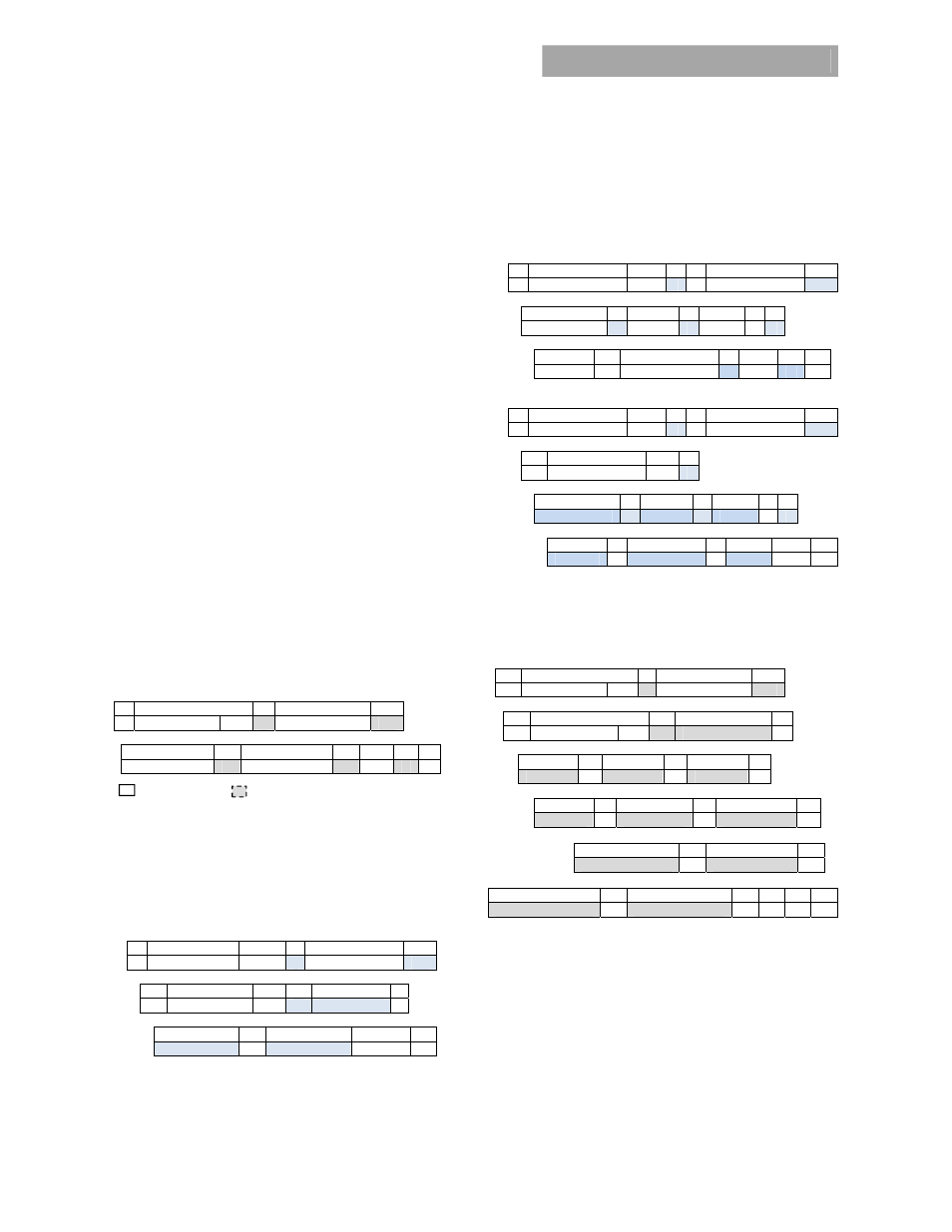
Standard instruction:
Up to two bytes of data may follow an
instruction depending on the required data content. Analog
data is always transmitted as LSB followed by MSB. PEC is
optional and includes the address and data fields.
1 8 1
8 1
S Slave
address Wr A Command
Code A
8 1 8 1
8
1
1
Low data byte
A High
data
byte A PEC A P
Master to Slave Slave to Master
SMBUS annotations; S – Start , Wr – Write, Sr – re-Start, Rd
– Read,
A – Acknowledge, NA – not-acknowledged, P – Stop
Standard READ:
Up to two bytes of data may follow a READ
request depending on the required data content. Analog
data is always transmitted as LSB followed by MSB. PEC is
mandatory and includes the address and data fields
.
1 7
1
1 8 1
S Slave
address Wr A Command
Code A
1 7 1
1 8
1
Sr Slave
Address Rd A
LSB A
8 1 8
1
1
MSB A PEC No-ack
P
Block communications:
When writing or reading more than
two bytes of data at a time BLOCK instructions for WRITE and
READ commands are used instead of the Standard
Instructions above to write or read any number of bytes
greater than two.
Block write format:
1
7 1
1
8 1
S
Slave address
Wr
A Command
Code A
8 1
8
1
8
1
Byte count = N
A Data
1 A Data
2 A
8 1
8
1
8
1
1
………. A Data
N
≤ 48
A PEC A P
Block read format:
1
7 1
1
8 1
S
Slave address
Wr
A Command
Code A
1 7 1
1
Sr Slave
Address Rd A
8 1
8
1
8
1
Byte count = N
A
Data 1 A Data 2
A
8 1
8
1 8 1 1
………. A
Data N ≤ 48
A
PEC NoAck P
An example of the block_read instruction is the
Read_std_parameters (D0h) command. This ‘manufacturer
specific’ command returns STATUS and ALARM register data,
output voltage, output current, and internal temperature in a
single read string.
1 8 1
8 1
S Slave
address Wr A Command Code
A
1 8 1
8
1
Sr Slave
address Rd A
Byte count = 11
A
8 1 8 1 8 1
Status-2 A Status-1 A Alarm-2 A
8
1 8 1 8 1
Alarm-1 A Voltage LSB
A
Voltage MSB
A
8 1 8 1
Current LSB
A
Current MSB
A
8 1 8 1
8
1
1
Temperature LSB
A
Temperature MSB
A PEC NA P
Linear Data Format
The definition is identical to Part II of the
PMBus Specification. All standard PMBus values, with the
exception of output voltage related functions, are
represented by the linear format described below Output
voltage functions are represented by a 16 bit mantissa. The
value of the exponent for output voltage functions is listed in
the Vout_mode command.