Car2012te series rectifier, Data sheet, Manufacturer-specific pmbus – GE Industrial Solutions CAR2012TE series User Manual
Page 14: Commands
GE
Data Sheet
CAR2012TE series rectifier
Input: 85Vac to 264Vac; Output: 12 Vdc @ 2000W; 3.3Vdc or 5 Vdc @ 4A
February 9, 2014
©2013 General Electric Company. All rights reserved.
Page 14
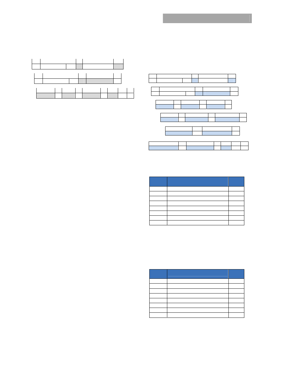
Read_FRU_ID (0x99,0x9A, 0x9E):
Returns FRU information
1 8 1
8 1
S Slave
address Wr A Command
0x9x A
1 8 1
8
1
Sr Slave
address Rd A
Byte count = x
A
8 1
8
1 8 1
8
1
1
high byte
A Byte… A low byte
A PEC NA P
Mfr_ID (0x99):
Manufacturer in ASCII – 5 characters
maximum,
General Electric – Critical Power represented as: GE-CP
Mfr_MODEL (0x9A):
Manufacturer model-number in ASCII –
16 characters, for this unit: CAR2012TEBXXZ01A
Mfr_serial (0x9E):
Product serial number includes the
manufacturing date, manufacturing location in up to 15
characters. For example:
13KZ51018193xxx, is decoded as;
13 – year of manufacture, 2013
KZ – manufacturing location, in this case Matamoros
51 – week of manufacture
018193xxx – serial #, mfr choice
note: if the additional xxx space is not utilized then F’s
are filled in, (i.e. 018193FFF), ensuring that the actual serial
number is clearly identified.
Manufacturer-Specific PMBus
TM
Commands
Many of the manufacturer-specific commands read back
more than two bytes
.
If more than two bytes of data are
returned, the standard SMBus
TM
Block read is utilized. In this
process, the Master issues a Write command followed by the
data transfer from the power supply. The first byte of the
Block Read data field sends back in hex format the number of
data bytes, exclusive of the PEC number, that follows. Analog
data is always transmitted LSB followed by MSB. A No-ack
following the PEC byte signifies that the transmission is
complete and is being terminated by the ‘host’.
Mfr_Specific Status and alarm registers:
The content and
partitioning of these registers is significantly different than
the standard register set in the PMBus™ specification. More
information is provided by these registers and they are either
accessed rapidly, at once, using the ‘multi parameter’ read
back scheme of this document, or in batches of two STATUS
and two ALARM registers.
Read_std_parameters (0xD0) :
This ‘manufacturer specific’
command is the basic read back returning STATUS and
ALARM register data, output voltage, output current, and
internal temperature data in a single read.
1 8 1
8
1
S Slave
address Wr A Command
Code A
1 8 1
8
1
Sr Slave
address Rd A Byte count = 10
A
8 1 8 1 8 1
Status-2 A Status-1 A Alarm-2 A
8
1 8 1 8 1
Alarm-1 A Voltage LSB
A
Voltage MSB
A
8 1 8 1
Current LSB
A
Current MSB
A
8 1 8 1
8
1
1
Temperature LSB
A Temperature MSB A PEC NA P
Read_Status_state (0xD1):
This command returns the two
STATUS register values using the standard ‘read’ format.
Status-2
Bit
Position
Flag
Default
Value
7 PEC
Error 0
6
Will restart
0
5 Invalid_Instruction 0
4
Power_Capacity [HL = 1]
x
3 Isolation
test
failed 0
2 Restarted_OK 0
1 Data
out_of_range 0
0
Remote ON [logic HI = 1]
x
Isolation test failed: The ‘system controller’ has to determine
that sufficient capacity exists in the system to take a power
supply ‘off line’ in order to test its isolation capability. Since
the power supply cannot determine whether sufficient
redundancy is available, the results of this test are provided,
but the ‘internal fault’ flag is not set.
Status-1
Bit
Position
Flag
Default
Value
7 X 0
6 Isolation_Test_OK 0
5 Internal_Fault 0
4 Shutdown 0
3
Service LED ON
0
2 External_Fault 0
1 LEDs_Test_ON 0
0 Output
ON x