GE Industrial Solutions Arc Vault Protection System User Manual
Page 46
Arc Vault™ Protection System
DEH-41483 Rev. 3
Maintaining the Switchgear
38
© 2011 General Electric All Rights Reserved
2. Check all bolts that hold cable terminals to the
connection bars for tightness.
3. Check the ground bus connection and mounting bolts
for tightness.
4. Check that all secondary control wiring connections
are tight and that all control cabling is intact.
OVERALL EQUIPMENT
Make the following checks on the complete switchgear
equipment.
1. Clean and inspect all painted surfaces and retouch
where necessary.
2. Check to see that all anchor bolts and other structural
bolts are tight.
3. Check that all device and instrument compartment
door latches operate properly.
4. If the switchgear is equipped with heaters, check to see
that all heaters are energized and operating.
PAINT REFINISHING
Indoor switchgear is finished with ANSI-61 gray acrylic
enamel paint (PPG W42713, GE part number 21525032650).
To refinish damaged areas, remove all loose paint, rust,
scale, oil or grease. Sand any scratches smooth using 220
grit paper or finer.
1. Apply a coat of good acrylic enamel primer (Sherman-
Williams E61 A 60,-GE part number 21525025200) with
a viscosity of approximately 24-32 seconds using a #2
Zahn cup. Reduce with D5B9 Xylol (GE part number
21525038000) if needed. Air dry the primer for a
minimum of 30 minutes, then apply the finish color coat
of acrylic enamel. The top coat should be applied within
24 hours for best adhesion.
2. If the area is to be spray-coated, thin the acrylic
enamel with D5B9 Xylol (GE part number 21525038000).
This thinning should only be necessary if the paint was
received in a five gallon drum or more The
recommended viscosity for the W42713 topcoat should
be 24-32 seconds with a #2 Zahn cup. The curing
schedule for PPG W42713 is dust free in 5 minutes,
touch in 30 minutes, handle in 60 minutes, full cure in 7
days. Both the primer (Sherwin-Williams E61 A 60) and
paint (PPG W42713) should be applied only when
temperature is above 55 degrees Fahrenheit.
3. Application of special paint will be per the
manufacturer’s Product Data Sheet which includes
instructions on thinning and application.
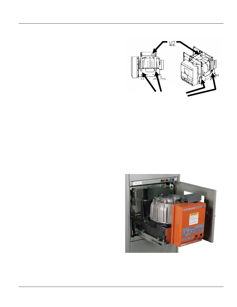
ARC VAULT LIFTING MECHANISM PT # GAVLD1
Figure 11-1 Lifting mechanism connection points
Position and connect the lifting mechanism to the Arc Vault
device as shown in Figure 11-1. There are two square
openings on the frame sides and two top hat shaped pins
connected to the frame. Slide out the rails located in the
cassette. With the lifting mechanism in place you can now
attach to the lifting hole to lift and position the device on
the rails using the four top hat shaped rolling pins. Be
careful that the pins are located properly on the rails before
disconnecting the lifting mechanism. Device can now be
rolled into the cassette to the disconnected position. Side
rails can be pushed into the cassette until seated.
Figure 11-2 Arc Vault device with extended rails and
roller pins in place
Connection Points