Caution, Notice – GE Industrial Solutions Arc Vault Protection System User Manual
Page 23
DEH-41483 Rev. 3
Arc Vault™ Protection System
Equipment
Installation
© 2011 General Electric All Rights Reserved
15
SECTION 4. EQUIPMENT INSTALLATION
GENERAL
This chapter contains complete instructions for installing
General Electric Arc Vault Low-voltage equipment.
CAUTION
Personnel installing this equipment must be familiar
with this instruction manual and all articles of the
National Electrical Code applicable to the installation
of this switchgear. In addition, all drawings, both
mechanical installation and electrical, must be
understood and strictly followed to prevent damage
to the switchgear or equipment being protected by
the switchgear.
NOTICE
Before installation work is started, it is important to
review all of the drawings provided, including the
General Electric equipment arrangement drawings,
site installation drawings, elementary and remote
connection drawings, mechanical connection
drawings, and the summary of equipment list.
All expendable hardware for shipping purposes only,
is painted yellow or tagged with yellow adhesive tape
and may be discarded at completion of the
installation phase.
Site Location
In general, the location of the switchgear equipment will
have been predetermined during the specification and/or
procurement of equipment phases. Indoor locations within
buildings impose certain requirements which must be met
so that the switchgear may operate efficiently with a
minimum of maintenance.
In locating the Arc Vault equipment, adequate aisle space
must be provided at the front and rear of the equipment to
ensure proper ventilation of and to allow service and
maintenance with the front and rear doors open. The
recommended aisle space is shown on the floor plan
supplied with the equipment drawings.
The switchgear equipment should be placed in an area
where clean, dry air is free to circulate around and above it.
Since air is taken into the equipment at the bottom of each
section and exhausted at the top, a location with good
airflow must be provided for efficient operation. A minimum
of 30 inches of clear space above the equipment is
recommended.
Foundation Requirements
For optimum performance of your General Electric
switchgear equipment, the foundation requirements
expressed in this chapter should be strictly adhered to.
NOTICE
The foundation for the outdoor switchgear must
provide proper drainage of ground and surface water
accumulations away from the equipment.
The foundation must be strong enough to prevent
sagging due to the weight of the switchgear structure
and to withstand the shock stress caused by the
opening of the breakers under fault conditions. The
shock loading is approximately 1.5 times the static
load.
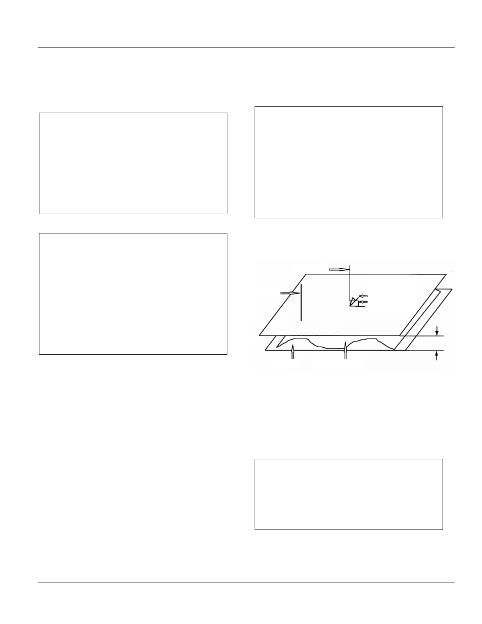
The foundation must be flat and level in all planes. Refer to
Figure 4-1 for definition of flat and level.
Figure 4-1 Definition of flat and level
Foundation Preparation
Refer to Figure 4-2 along with the owner's foundation
construction drawings, and the General Electric
supplemental installation drawings. Although the indoor
switchgear equipment can be mounted directly on a
smooth, level floor, it is recommended that recessed steel
channels be installed for supporting the equipment. Anchor
bolts and channels are to be provided by the purchaser.
NOTICE
When the equipment is installed on a surface subject
to impact (shock) loads due to operating conditions or
environmental seismic (earthquake) conditions, the
anchor bolts should be fabricated of medium carbon
steel (grade 5 load rating).
The floor channels under the front and rear switchgear
anchor points (see Figure 4-2) should be embedded in a
level concrete slab with their top surfaces flush with the
finished floor. It is essential that these steel channels be
level and aligned with each other prior to final anchoring, to
.
062"
Plumb line
Plane#1
Plane#2
Surface of pad
Perpendicular
on both axes
to within 0.25"
over 10' span