Notice – GE Industrial Solutions Arc Vault Protection System User Manual
Page 26
Arc Vault™ Protection System
DEH-41483 Rev. 3
Equipment Installation
18
© 2011 General Electric All Rights Reserved
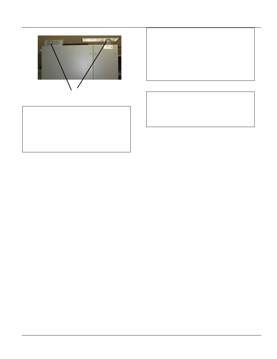
Figure 4-4 Lifting plate location
NOTICE
If the equipment line-up was split into shipping
sections, the lifting plates on corners of adjacent
sections shown in Figure 4-4 must be removed.
Failure to remove these plates will interfere with
mating adjacent sections and prevent installation of
bus splice plates, structure tie plates, etc.
Arc Vault sections are equipped with lifting plates. These
plates can be left in place when the Arc Vault section is
positioned separate from the line up. Lifting plates must be
removed if section will be positioned directly next to the
switchgear line up.
Once the lifting plates have been removed, they may be
discarded.
NOTICE
If the lifting plates must be reassembled on the
equipment for lifting, they must be moved to
locations where unused screw holes are available,
generally by shifting the plate horizontally on the
mounting surface one bolt-hole from its previous
location. When remounting the lifting plates, torque
the mounting bolts to 7-9 ft-lbs.
NOTICE
All mating sections of the equipment line-up
(including transformer, if applicable) must be securely
fastened together prior to tightening anchor bolts
fastening the equipment to the mounting surface.
2. REMOVE THE SHIPPING SKIDS-The equipment is fastened
to the shipping skids with 3/8-3 lag screws through the
equipment anchoring holes. See Figure 4-6.
Equipment shipping sections up to 10 feet long will be
fastened to the skids with four lag screws, one in each
corner. The shipping skid and lag screws are expendable
material and may be disposed of at the purchaser's
discretion.
3. FASTEN SECTIONS TOGETHER-After placement of the
equipment and installing the anchor bolts loosely, the
various shipping sections must be rigidly fastened together.
Through-bolts fasten each section of the switchgear
equipment to the adjacent section. Figure 4-5 shows the
location of the through-bolts.
Lifting Plate