Warning – GE Industrial Solutions Arc Vault Protection System User Manual
Page 38
Arc Vault™ Protection System
DEH-41483 Rev. 3
Operation
30
© 2011 General Electric All Rights Reserved
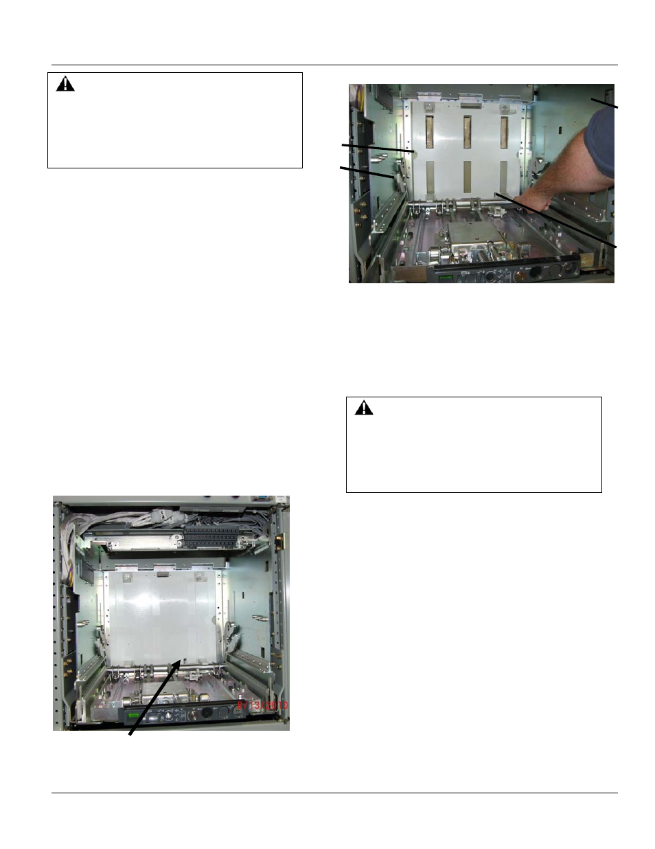
Removing Shutter Units (on a de-engergized cubicle)
Visual inspection of primary stab tips can be made by first
removing the breaker and opening the shutters manually.
This is done by rotating the actuating lever that opens the
shutter (See Figure 7-8). If it is necessary to perform work
on the primary disconnects, the shutter unit and the stab
tip bracing must be removed. To remove the shutter,
remove the four screws in the corners of the shutter and
carefully remove shutter unit.
To remove these shutter units, proceed as follows.
1. The shutter is mounted by four screws on the
horizontal stab tip braces located at each side of the
rear of the breaker compartment. See Figure 7-8.
2. Take out two slotted head screws on each side of the
frame and carefully remove the shutter unit.
3. Carefully remove the entire shutter frame.
4. The frame is then maneuvered forward past the
racking cams on each side, then upward and forward
out of the cassette.
Figure 7-8 Arc Vault cassette shutter assembly
Figure 7-9 Arc Vault shutter unit
1. Side frame assembly (right)
2. Racking Cam
3. Shutters
4. Shutter actuator
Installing a Shutter Unit (in a de-energized cubicle)
WARNING
Unless the proper precautions are taken, the
installation of a shutter unit presents the hazard of
electrical shock and burn. Do not install the shutter
unit unless the equipment has been de-energized.
Failure to do this can result in serious injury.
To install these shutter units, proceed as follows.
1. Carefully maneuver the shutter frame into the
compartment, first lifting it over the racking cams on
each side wall of the cassette. Make sure the shutter
fits over the shutter actuator at the bottom of the
cassette.
2. Position the shutter frame against the stab tip braces
and align the holes with the stand off on the braces.
3. After the holes are aligned with the threaded stand offs,
attach the shutter in 4 corner locations using the bolts
supplied.
4. Check the operation of the moveable shutters by
actuating the shutter level on the bottom of the
cassette.
WARNING
Unless the proper precautions are taken, the removal
of a shutter unit presents the hazard of electrical
shock and burn. Do not remove the shutter unit
unless the equipment has been de-energized. Failure
to do this can result in serious injury
Shutter actuating lever
3
4
1
2