Disch charge, Warning – GE Industrial Solutions Arc Vault Protection System User Manual
Page 34
Arc Vault™ Protection System
DEH-41483 Rev. 3
Testing and inspection
26
© 2011 General Electric All Rights Reserved
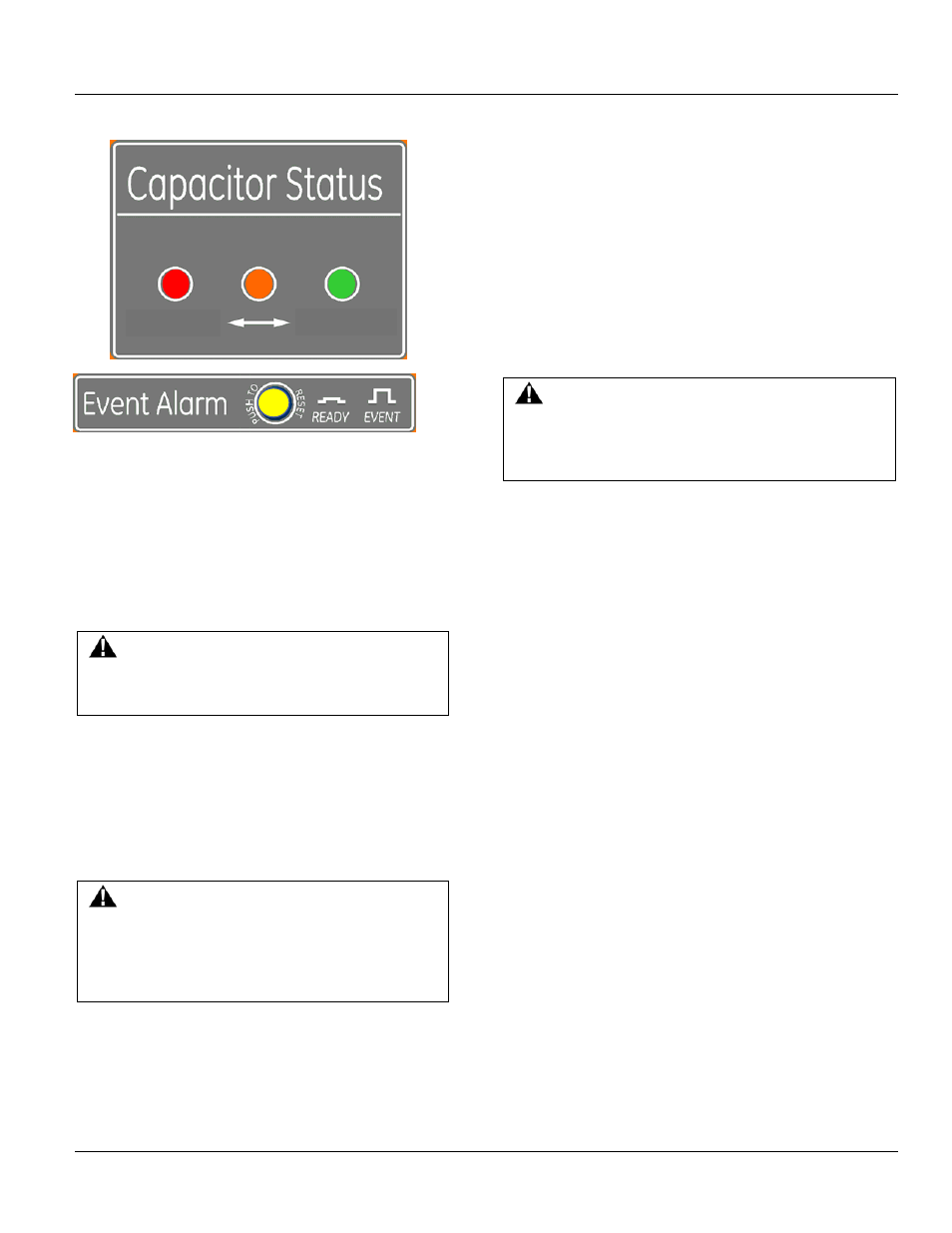
Disch
Charge
Reset the pop out indicator by depressing the yellow
indicator. This procedure may be repeated if desired.
ARC VAULT RELAY
The calibration of the Arc Vault relay trip system is
comprised of the following components.
• Relay
• Current transformers Class C50 or better 5000:5A
• Shunt trip on the tripable device
WARNING
Correct current transformer class and rating is critical
to proper system function.
All control components, except the CT’s and the Shunt trip
are integrally mounted in the Arc Vault Protection System
stack in drawout construction. The Relay is automatically
connected to the device via a drawout secondary
disconnect block.
WARNING
Never disengage the relay without shorting the
Current transformers properly. This will open-circuit
the current sensors, allowing dangerous and
damaging voltages to develop.
FINAL STEPS TO BE TAKEN BEFORE ENERGIZING
EQUIPMENT
The following steps should be taken before energizing the
equipment.
1. Manually exercise all circuit breakers that the, Arc Vault
relay will be controlling, and other operating
mechanisms to make certain they are properly aligned
and operate freely.
2. Conduct an electrical insulation resistance test to make
sure the switchgear is free from short circuits and
grounds. This should be done both phase-to-ground
and phase-to-phase with the switches or circuit
breakers both opened and closed. The Arc Vault Device
shall be in the discharged state. This test should be
performed with a 1000 volt meggar. Disconnect all
control circuits before checking resistance.
3. Upstream breaker must be tested to verify it is
functional and can clear the fault in less than 5 cycles.
WARNING
Upstream breaker is responsible for interrupting arcing
event. Make sure breaker is functional upon trip signal.
Failure to do so may result in death or serious injury.
3A. Verify CTs are properly connected.
4. Check any electrical relays, meters, or instrumentation
to determine that connections are made properly and
the devices function properly.
5. Electrically exercise all electrically operated circuit
breakers, and other mechanisms (but not under load),
to determine that the devices operate properly. An
auxiliary source of control power may be necessary to
provide power to the electrical operators.
6. Make certain that field wiring is clear of live bus and,
where necessary, physically secured to withstand the
effects of fault currents.
7. Check to determine that all grounding connections are
made properly.
8. Remove all debris, scrap wire, etc., from the switchgear
interior before closing the enclosure.
9. Install covers, close doors, and make certain that no
wires are pinched and that all enclosure parts are
properly aligned and tightened.
Discharged
Charged