GE Industrial Solutions Arc Vault Protection System User Manual
Page 35
DEH-41483 Rev. 3
Arc Vault™ Protection System
Operation
© 2011 General Electric All Rights Reserved
27
SECTION 7. OPERATION
ARC VAULT DEVICE OPERATION
Included below are abbreviated operating instructions for
Arc Vault. Before activation of the Arc Vault or operation of
the switchgear equipment, thoroughly read, and be familiar
with this Arc Vault manual.
All Arc Vault devices are manually operated. They are
equipped with an integral charging push button marked
“Push to Charge” on the front of the escutcheon.
The charge indicator will show CHARGED by illuminating
the green LED when the charge button is pressed to the “in”
position.
A mechanically operated DISCHARGE button mounted on
the device escutcheon discharges the unit when pressed to
the “in” position.
ARC VAULT DRAWOUT OPERATION
Arc Vault Positions
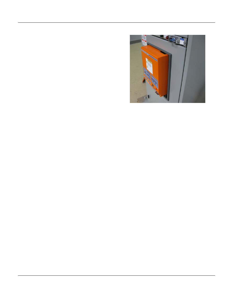
Refer to Figure 7-1. The drawout operation features four
positions:
1. CONNECTED - In the CONNECTED position, the primary
and secondary disconnects are fully engaged. The
device must be discharged before it can be racked out
of this position.
2. TEST - When in the TEST position, the primary contacts
are disconnected, but the secondary contacts remain
engaged. This allows test firing the device without
creating a fault on the primary circuit.
3. DISCONNECTED - In the DISCONNECTED position,
neither primary nor secondary contacts are made. The
Device may be racked between these three positions
with the compartment door closed and latched.
4. WITHDRAWN - With the door open, the device can be
rolled out manually from the DISCONNECTED to the
WITHDRAWN position. Here, the device is completely
out of its compartment, ready for removal.
Figure 7-1 Arc Vault gear shown in disconnected position
Drawout Operation
The device is supported on the drawout rails mounted on
the side walls of the cassette. The Arc Vault device has two
wheels on each side of the device frame that rest on each
drawout rail.
Motion is provided by a mechanism mounted on the
bottom of the cassette. This mechanism drives racking
cams which engage pins anchored to each side of the
device.
The cams are driven by a removable racking handle or
remote racker which engages the mechanism. The handle
is inserted through an opening in the cassette escutcheon
below the device.
Turning the handle in a clockwise direction drives the device
into the compartment. As the device disconnect fingers
engage the stab tips, a high force will be felt. Turn the
racking handle and verify position by using the alignment
markers on the side of the device or indicator barrel.
The indicator barrel should clearly show CONNECTED.
The position of the device is given by the position indicator
in the cassette escutcheon as it moves through the door
cutout. Racking position can also be verified by using the
alignment markers on the side of the device.
FRONT DOORS
Operation
The front access doors on all standard Arc Vault equipment
are hinged and equipped with a ¼-turn latch, Fig. 7-3. To
open the door, rotate the knob clockwise ¼ turn.
Door Removal
1. Open door.