Warning, Caution, Notice – GE Industrial Solutions Arc Vault Protection System User Manual
Page 11
DEH-41483 Rev. 3
Arc Vault™ Protection System
Receiving, Handling and Storage
© 2011 General Electric All Rights Reserved
3
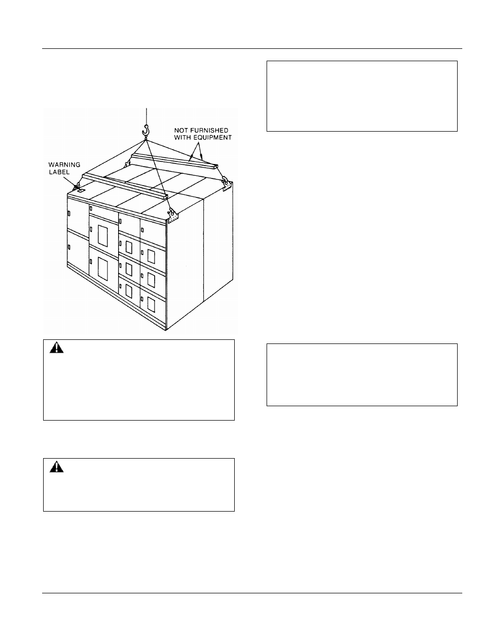
Example: Switchgear Section Weight = 2,000 pounds. The
crane and the four lift cables must have a minimum load
lifting capacity of 4,000 pounds.
Figure 2-2 Recommended lifting method
WARNING
The angle between the cables and the top of the
equipment must be at least 45 degrees. If this is not
possible because of lack of headspace, spreader bars
must be used. Also, lift cables with greater load
capability may be necessary, depending upon the
angle between the cables and the crane hook.
Connect a cable from the crane to the four lifting plates
located on the top-front and rear of the indoor
switchgear. See Figure 2-2.
WARNING
Do not stand under switchgear while it is being
moved. Serious injury may occur if the cables or
lifting device fail.
CAUTION
Gently lower the switchgear section onto the level site
location. If the switchgear is roughly handled or
jarred, it is possible to damage or misalign internal
components.
Rollers
If crane facilities are not available, the equipment may be
moved into position by means of construction rollers
placed under the shipping skids. The switchgear may be
raised enough for the placement of rollers by means of a
fork lift or jack.
There should never be less than four rollers under the
equipment unless the line-up is less than five feet long.
Use one roller for each 18 inches of equipment length.
Forklifts
When using a forklift to raise the line-up to position rollers
underneath, proceed as follows:
1. Expand forklift tines to their maximum (widest)
extension.
2. Carefully insert tines of forklift below one side of the
switchgear line-up at the approximate center of the
panel as shown in Figure 2-3.
NOTICE
Do not attempt to lift or move the equipment with a
forklift positioned in the front or rear of the
equipment. Equipment may tip over and get
damaged.
1. Raise equipment and position one roller under the
skids close to the raised end of the line-up.
2. Carefully lower the gear until it rests on the roller as
shown in Figure 2-4.
3. Repeat the lifting process at the other end and place
the appropriate number of rollers under the skids
spacing them evenly across the width of the line-up.