Warning – GE Industrial Solutions Arc Vault Protection System User Manual
Page 21
DEH-41483 Rev. 3
Arc Vault™ Protection System
Description
© 2011 General Electric All Rights Reserved
13
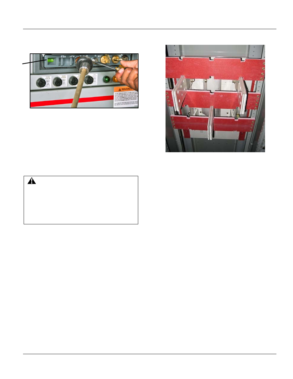
Figure 3-9 Racking handle for movement of Arc Vault
1. Arc Vault device position indicator
Movement of the Arc Vault between the CONNECTED, TEST,
and DISCONNECTED positions is performed by the use of a
racking handle, see Figure 3-9, which engages the racking
mechanism mounted on the cassette. An optional remote
racking device is also available. Movement to the
WITHDRAWN position is manually performed after opening
the compartment door. These positions are illustrated and
described more fully in SECTION 5 .
WARNING
The door should NOT be opened when the Arc Vault is
charged and in the CONNECTED position. Although
the device compartment door may be opened in any
position, it is recommended that the door only be
opened when the Arc Vault is in the DISCONNECTED
or WITHDRAWN position.
On a 480V nominal system the Arc Vault Protection System
can be applied on systems with available current up to
65KA.
Feeder Cable Compartment
The rear cable and terminal compartment, Figure 3-10,
provides for cable installation and terminations. The cable
bending space meets the requirements of the National
Electric Code. Various arrangements of single or double
cable terminals are provided, depending upon the
purchaser's requirements.
When specified, racks for the support of feeder cables are
located in the cable compartment. The actual support of
the cables is provided by lashing them to these racks.
Also located in the cable compartments are provisions for
terminating control wires between external devices and
control circuits within the switchgear equipment.
Figure 3-10 Cable termination provisions
Cable lugs - mechanical type
When furnished, the terminal boards, for such connections
are located in an enclosed vertical wiring trough mounted
on the side of the cable compartment. The trough is of steel
construction with bolted covers to provide an isolation
barrier between the control wiring and the adjacent power
cables.
GROUND BUS
All General Electric AKD-20 switchgear sections are
grounded to the internal equipment ground bus (4), Figure
3-11, located at the bottom of the cable compartment.
1