Caution – GE Industrial Solutions Arc Vault Protection System User Manual
Page 29
DEH-41483 Rev. 3
Arc Vault™ Protection System
Equipment
Installation
© 2011 General Electric All Rights Reserved
21
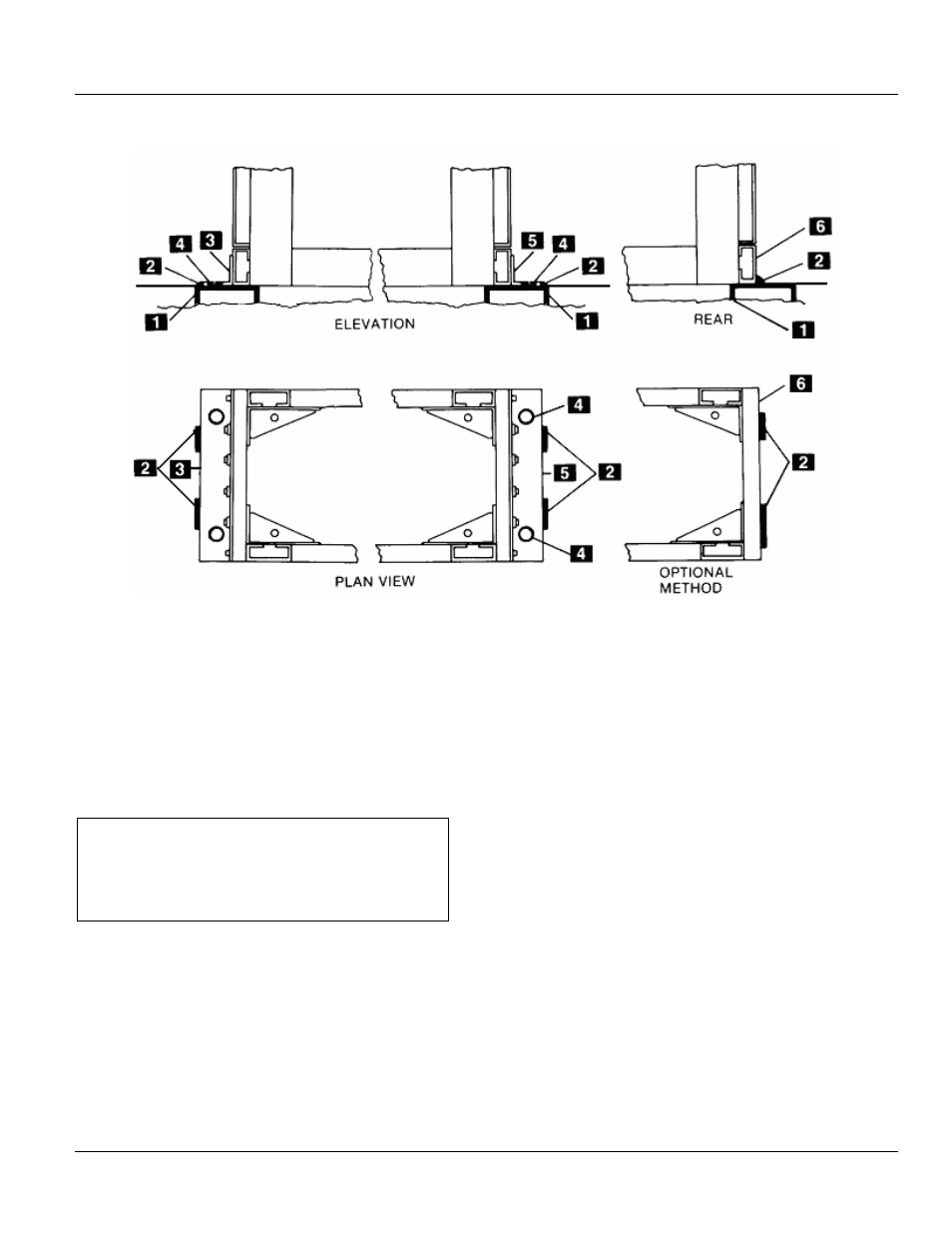
Figure 4-7 Indoor equipment weld anchoring
1. Channel sill
2. 3/16-inch fillet weld
3. Front sill angle
4. Plug weld in anchor bolt hole
5. Rear sill angle
6. Rear width post
The four anchor bolts should be tightened with a torque of
45-55 ft-lbs.
CAUTION
If the equipment is to be subjected to operational or
environmental (seismic) shock loading, the factory
must be consulted for anchoring recommendations.
Control Wire Connections
For external control wiring, refer to Figure 4-3 for
switchgear cable area dimensions, and connect the control
wires to the switchgear section as follows.
1. When control conduits enter the switchgear from
below, they should not extend more than one inch
above the floor. The control wires may be pulled
through the conduits before or after the switchgear is
installed.
2. Route the control wires from the conduits through the
wiring trough at the side of the cable compartment,
shown in Figure 4-3. Connect the cables to the terminal
blocks in accordance with the connection diagrams for
the equipment.
3. If the control conduits enter from above, drill the top
cover within the available space indicated. See Figure
4-3. Control wires should be routed to the wiring trough
and connected to the terminal blocks as described
previously.
Power Cable Connections
Connect the main cables to the main lugs. Before any main
cable connections are made, the cables should be identified
to indicate their phase relationship with the equipment.
Adequate electrical and mechanical clearances must be
provided between conduit, cables, and bus.