B&B Electronics GW-7553 - Manual User Manual
Page 8
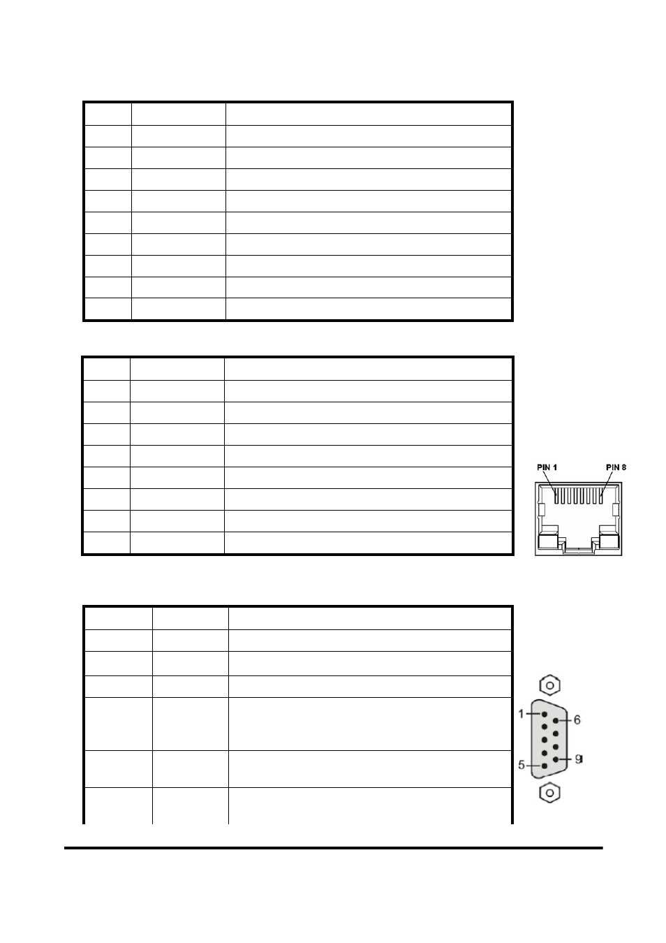
Table 3 9-pin screw terminal block
Pin Name
Description
1
CTS
Clear to Send of RS-232
2
RTS
Request to Send of RS-232
3
RX
Receive Data of RS-232
4
TX
Transmit Data of RS-232
5
GND
GND of RS-232
6 -
N/A
7 -
N/A
8
+VS
V+ of Power Supply(+10 ~ +30 V
DC
)
9
GND
GND of Power Supply
Table 4 RJ-45 socket
Pin Name
Description
1 TX+
TX+
output
2 TX-
TX-
output
3 RX+
RX+
input
4 -
N/A
5 -
N/A
6 RX-
RX-
input
7 -
N/A
8 -
N/A
Table 5 PROFIBUS DB9 Female Connector
Pin Name
Description
1 -
N/A
2 -
N/A
3
B
Non-inverting Bus Line
4
ISODE
Isolated DE output for use in PROFIBUS
applications where the state of the isolated drive
enable node needs to be monitored.
5
GND
Power supply ground for the first node and the last
node
6
VP
+5V Power Supply for the first node and the last
node
GW-7553 PROFIBUS/Modbus TCP Gateway User Manual (Version 1.00, Dec/2008) PAGE: 8
- USOPTL4DR-LS - Datasheet (2 pages)
- ZXT9-IOA-KIT - Manual (75 pages)
- ADAM-6066 - Manual (272 pages)
- 855-11619--57 - Datasheet (2 pages)
- 851-10904 - Datasheet (2 pages)
- SS-BLT-100PR - Quick Start Guide (1 page)
- ISOCON-6 - Datasheet (2 pages)
- I-7060 - Manual (64 pages)
- AMU864 - Datasheet (2 pages)
- 714FX6-SC_ST - Manual (154 pages)
- 422LP25R - Datasheet (2 pages)
- ZP9D-115RM-LR - Manual (54 pages)
- EKI-6311GN-EU - Manual (56 pages)
- ZZ24D-NA(NB,NC,ND)-SR - Quick Start Guide (4 pages)
- ESCLP-100 - Manual (23 pages)
- 806-39753 - Datasheet (1 page)
- 485SD9RJ - Datasheet (1 page)
- 712FX4-SC_ST - Manual (154 pages)
- 850-18610 - Manual (18 pages)
- ESW208 Series - Datasheet (2 pages)
- VESR321_ML_SL - Quick Start Guide (3 pages)
- OP10 - Datasheet (1 page)
- RT3G-300_310_320_330_340-W - Configuration Manual (79 pages)
- EIRHP305-T - Datasheet (2 pages)
- EIRSP1 - Datasheet (1 page)
- 422TTL33 - Datasheet (2 pages)
- 485DRCI - Quick Start Guide (2 pages)
- I-7021_P - Datasheet (2 pages)
- NTSA-CAT5E - Datasheet (2 pages)
- 485COSR - Datasheet (2 pages)
- 855-10619--57 - Datasheet (2 pages)
- UH401SL_2KV - Datasheet (2 pages)
- 105FXE-SC(ST)-15-POE - Manual (19 pages)
- 102MC-FL_SC_ST - Manual (23 pages)
- CBL00302 - Datasheet (1 page)
- 850-18100--27 - Datasheet (2 pages)
- 850-10953-DC - Datasheet (2 pages)
- ESR904 - Datasheet (2 pages)
- 308TX-N - Datasheet (3 pages)
- 422LP25N - Datasheet (2 pages)
- 708FX2-SC_ST - Datasheet (3 pages)
- MESR321_SL_ML - Datasheet (2 pages)
- SL2736-698 - Quick Start Guide (8 pages)
- I-7188E Series - Datasheet (1 page)
- ANT-PAD58-19 - Datasheet (1 page)