B&B Electronics GW-7553 - Manual User Manual
Page 15
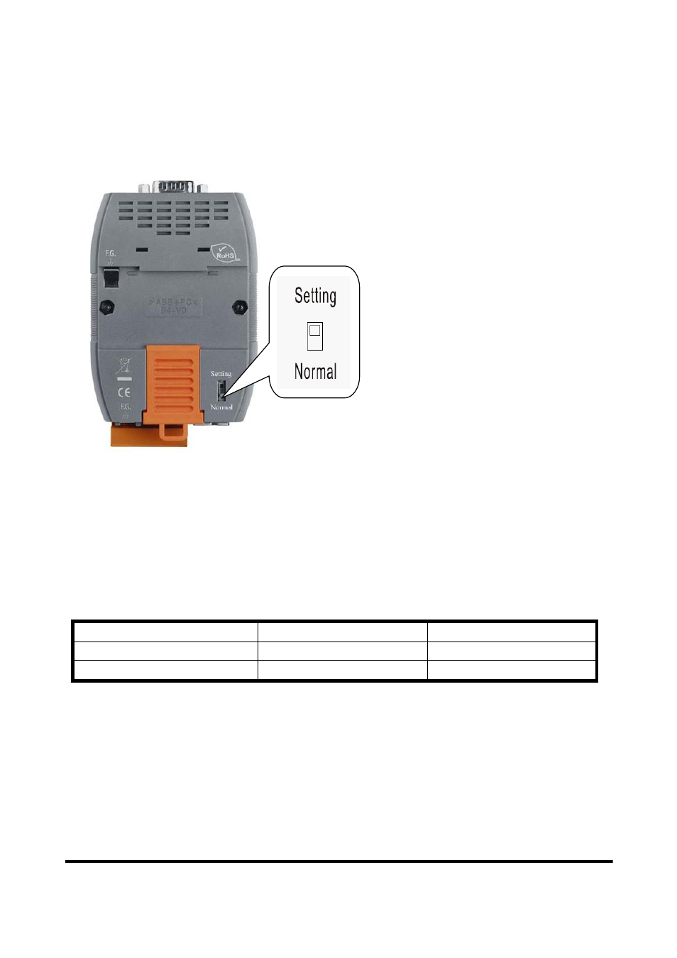
setting mode. In the normal situation, it needs to set the DIP switch to the “Normal”
position. In this case, the GW-7553 module can communicate with Modbus devices.
When the user sets the DIP switch to the “Setting” position, the GW-7553 module can
communicate with the utility to set the safe value and network configuration.
GW-7553 PROFIBUS/Modbus TCP Gateway User Manual (Version 1.00, Dec/2008) PAGE: 15
Figure 10 DIP switch of the GW-7553
PS:
There are two kinds of methods to enable the setting mode of the GW-7553. The user
can change the position of the DIP switch or set the control bit (please refer section
4.6.2 Output data area and communication command) to enable the setting mode of
the GW-7553, as shown in table 10.
Table 10 Mode of GW-7553
Mode
SM(control bit)=0
SM(control bit)=1
DIP switch=Normal
operation mode
setting mode
DIP switch =Setting
setting mode
setting mode
- USOPTL4DR-LS - Datasheet (2 pages)
- ZXT9-IOA-KIT - Manual (75 pages)
- ADAM-6066 - Manual (272 pages)
- 855-11619--57 - Datasheet (2 pages)
- 851-10904 - Datasheet (2 pages)
- SS-BLT-100PR - Quick Start Guide (1 page)
- ISOCON-6 - Datasheet (2 pages)
- I-7060 - Manual (64 pages)
- AMU864 - Datasheet (2 pages)
- 714FX6-SC_ST - Manual (154 pages)
- 422LP25R - Datasheet (2 pages)
- ZP9D-115RM-LR - Manual (54 pages)
- EKI-6311GN-EU - Manual (56 pages)
- ZZ24D-NA(NB,NC,ND)-SR - Quick Start Guide (4 pages)
- ESCLP-100 - Manual (23 pages)
- 806-39753 - Datasheet (1 page)
- 485SD9RJ - Datasheet (1 page)
- 712FX4-SC_ST - Manual (154 pages)
- 850-18610 - Manual (18 pages)
- ESW208 Series - Datasheet (2 pages)
- VESR321_ML_SL - Quick Start Guide (3 pages)
- OP10 - Datasheet (1 page)
- RT3G-300_310_320_330_340-W - Configuration Manual (79 pages)
- EIRHP305-T - Datasheet (2 pages)
- EIRSP1 - Datasheet (1 page)
- 422TTL33 - Datasheet (2 pages)
- 485DRCI - Quick Start Guide (2 pages)
- I-7021_P - Datasheet (2 pages)
- NTSA-CAT5E - Datasheet (2 pages)
- 485COSR - Datasheet (2 pages)
- 855-10619--57 - Datasheet (2 pages)
- UH401SL_2KV - Datasheet (2 pages)
- 105FXE-SC(ST)-15-POE - Manual (19 pages)
- 102MC-FL_SC_ST - Manual (23 pages)
- CBL00302 - Datasheet (1 page)
- 850-18100--27 - Datasheet (2 pages)
- 850-10953-DC - Datasheet (2 pages)
- ESR904 - Datasheet (2 pages)
- 308TX-N - Datasheet (3 pages)
- 422LP25N - Datasheet (2 pages)
- 708FX2-SC_ST - Datasheet (3 pages)
- MESR321_SL_ML - Datasheet (2 pages)
- SL2736-698 - Quick Start Guide (8 pages)
- I-7188E Series - Datasheet (1 page)
- ANT-PAD58-19 - Datasheet (1 page)