5 led status indicator – B&B Electronics GW-7553 - Manual User Manual
Page 13
GW-7553 PROFIBUS/Modbus TCP Gateway User Manual (Version 1.00, Dec/2008) PAGE: 13
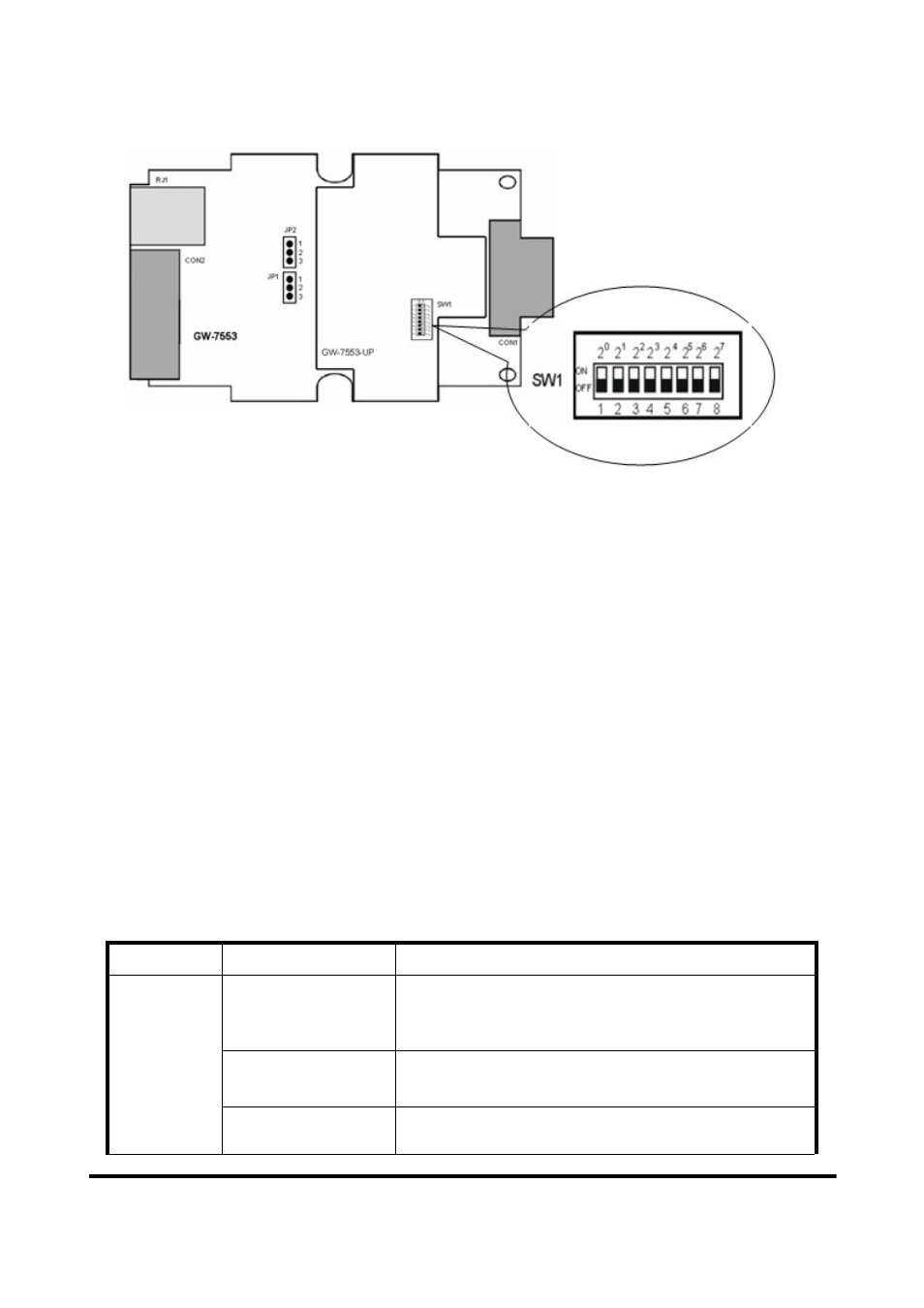
Figure 8: DIP switch
Each Slave must have a unique valid address (1 to 125) in order to be able to
communicate with the Master. To change the address by using the configuration
tool it is necessary to first set the address stored in the EEPROM to 126. This is
done by setting the DIP switch to 255 in the power off state. Switching the
module on is forcing the module to change its address in the EEROM to 126. In
the next step switch the module off and change the DIP switch setting to any
value from 126 to 254. This step is necessary in order to prevent the module to
change its address in the EEPROM to 126 every time it is powered on. The
configuration tool can now assign the Slave a new address.
2.5 LED status indicator
The GW-7553 provides three LEDs to indicate the statuses of the GW-7553
module. The position of LEDs and descriptions are shown in table 9 and figure 9.
Table 9: LED status description
LED Name
Status
Description
flash
When the GW-7553 acts as a Modbus Slave device
and receiving query message form Modbus Master
device, PWR led will flash.
on
Power supply is ok.
The firmware has loaded.
PWR
off
Power supply has failed.