Rainbow Electronics DS2182A User Manual
Page 4
DS2182A
041995 4/22
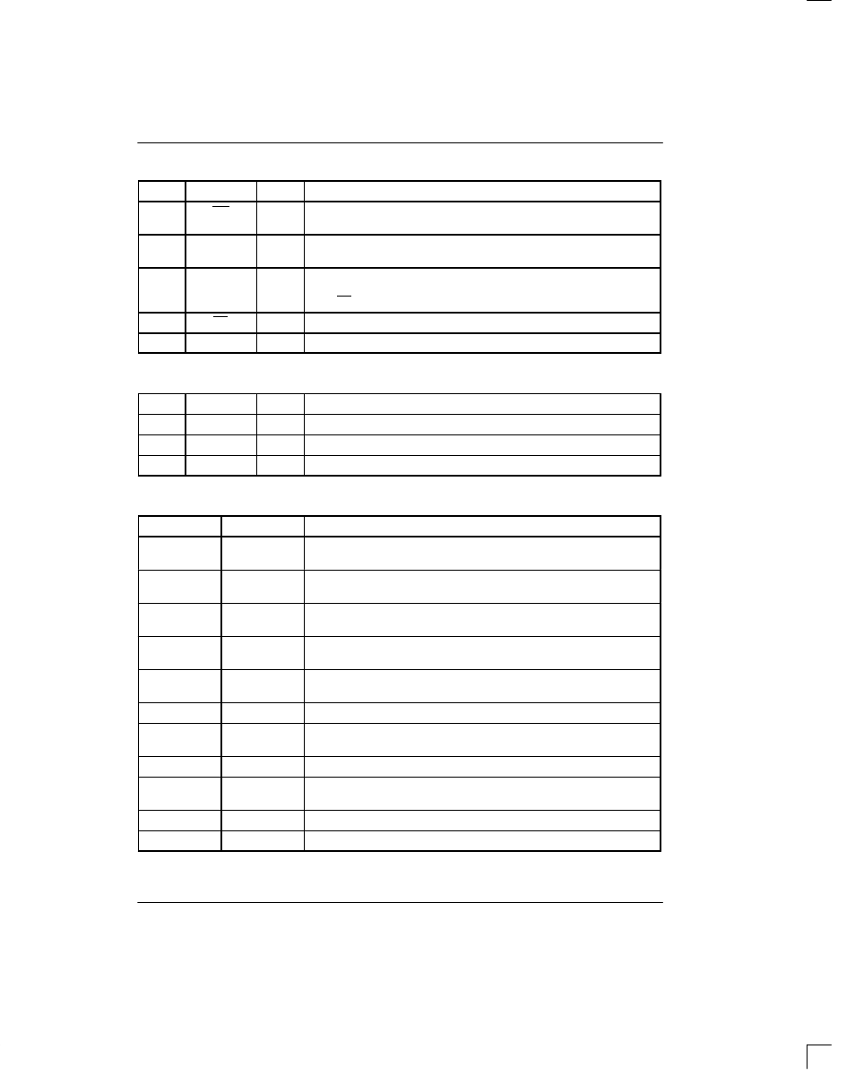
PORT PIN DESCRIPTION Table 2
PIN
SYMBOL
TYPE
DESCRIPTION
1
INT
O
Receive Alarm Interrupt. Flags host controller during alarm conditions.
Active low; open drain output.
2
SDI
I
Serial Data In. Data for onboard registers. Sampled on rising edge of
SCLK.
3
SDO
O
Serial Data Out. Control and status information from onboard registers.
Updated on falling edge of SCLK; tri-stated during serial port write or
when CS is high.
4
CS
I
Chip Select. Must be low to read or write the serial port.
5
SCLK
I
Serial Data Clock. Used to read or write the serial port registers.
POWER AND TEST PIN DESCRIPTION Table 3
PIN
SYMBOL
TYPE
DESCRIPTION
14
V
SS
–
Signal Ground. 0.0 volts.
20
TEST
I
Test Mode. Tie to V
SS
for normal operation.
28
V
DD
–
Positive Supply. 5.0 volts.
REGISTER SUMMARY Table 4
REGISTER
ADDRESS
DESCRIPTION/FUNCTION
BVCR2
0000
Bipolar Violation Count Register 2. LSW of a 16-bit presettable counter
that records individual bipolar violations.
BVCR1
0001
Bipolar Violation Count Register 1. MSW of a 16-bit presettable count-
er that records individual bipolar violations.
CRCCR
0010
CRC Error Count Register. 8-bit presettable counter that records CRC6
errored words in the 193E frame mode.
OOFCR
0011
OOF Count Register. 8-bit presettable counter that records OOF events.
OOF events are defined by RCR1.5 and RCR1.6.
FECR
0100
Frame Error Count Register. 8-bit presettable counter that records indi-
vidual bit errors in the framing pattern.
RSR1
0101
Receive Status Register 1. Reports alarm conditions.
RIMR1
0110
Receive Interrupt Mask Register 1. Allows masking of individual alarm-
generated interrupts from RSR1.
RSR2
0111
Receive Status Register 2. Reports alarm conditions.
RIMR2
1000
Receive Interrupt Mask Register 2. Allows masking of individual alarm-
generated interrupts from RSR2.
RCR1
1001
Receive Control Register 1. Programs device operating characteristics.
RCR2
1010
Receive Control Register 2. Programs device operating characteristics.