Rainbow Electronics T89C51CC01 User Manual
Page 96
96
T89C51CC01
Rev. D – 17-Dec-01
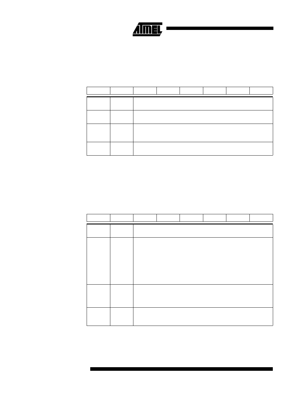
Table 53. CANPAGE Register
CANPAGE (S:B1h)
CAN message object Page
Register
Reset Value: 0000 0000b
Table 54. CANCONCH Register
CANCONCH (S:B3h)
CAN message object Control
and DLC Register
7
6
5
4
3
2
1
0
CHNB 3
CHNB 2
CHNB 1
CHNB 0
AINC
INDX2
INDX1
INDX0
Bit
Number
Bit
Mnemonic
Description
7-4
CHNB3:0
Selection of message object number
The available numbers are: 0 to 14 (see Figure 31).
3
AINC
Auto increment of the index (active low)
0 - auto-increment of the index (default value).
1 - non-auto-increment of the index.
2-0
INDX2:0
Index
Byte location of the data field for the defined message object (see Figure 31).
7
6
5
4
3
2
1
0
CONCH 1
CONCH 0
RPLV
IDE
DLC 3
DLC 2
DLC 1
DLC 0
Bit
Number
Bit
Mnemonic
Description
7-6
CONCH1:
0
Configuration of message object
CONCH1 CONCH0
0 0: disable
0 1: Launch transmission
1 0: Enable Reception
1 1: Enable Reception Buffer
NOTE:
The user must re-write the configuration to enable the corresponding bit in the
CANEN1:2 registers.
5
RPLV
Reply valid
Used in the automatic reply mode after receiving a remote frame
0 - reply not ready.
1 - reply ready & valid.
4
IDE
Identifier extension
0 - CAN standard rev 2.0 A (ident = 11 bits).
1 - CAN standard rev 2.0 B (ident = 29 bits).