Rainbow Electronics T89C51CC01 User Manual
Page 93
93
T89C51CC01
Rev. D – 17-Dec-01
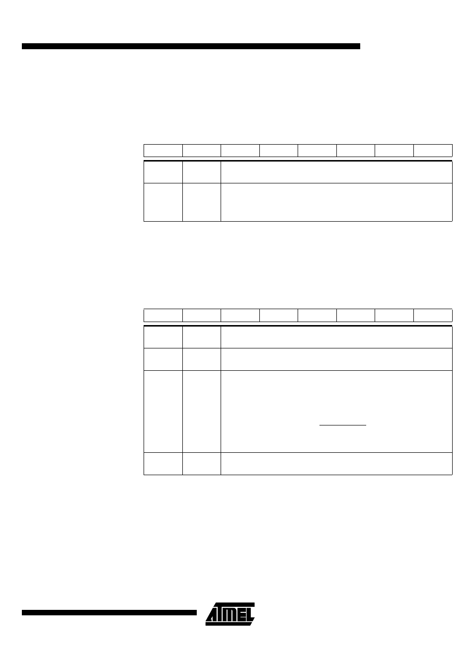
Table 49. CANIE2 Register
CANIE2 (S:C3h)
CAN Enable Interrupt message
object Registers 2
Reset Value: 0000 0000b
Table 50. CANBT1 Register
CANBT1 (S:B4h)
CAN Bit Timing Registers 1
Note:
The CAN controller bit timing registers must be accessed only if the CAN controller is dis-
abled with the ENA bit of the CANGCON register set to 0.
See Figure 35.
No default value after reset.
7
6
5
4
3
2
1
0
IECH 7
IECH 6
IECH 5
IECH 4
IECH 3
IECH 2
IECH 1
IECH 0
Bit
Number
Bit
Mnemonic
Description
7-0
IECH7:0
Enable interrupt by message object
0 - disable IT.
1 - enable IT.
IECH7:0 = 0b 0000 1100 -> Enable IT’s of message objects 3 & 2.
7
6
5
4
3
2
1
0
-
BRP 5
BRP 4
BRP 3
BRP 2
BRP 1
BRP 0
-
Bit
Number
Bit
Mnemonic
Description
7
-
Reserved
The value read from this bit is indeterminate. Do not set this bit.
6-1
BRP5:0
Baud rate prescaler
The period of the CAN controller system clock Tscl is programmable and
determines the individual bit timing.
0
-
Reserved
The value read from this bit is indeterminate. Do not set this bit.
Tscl =
BRP[5..0] + 1
Fcan