Rainbow Electronics T89C51CC01 User Manual
Page 27
27
T89C51CC01
Rev. D – 17-Dec-01
Reset Value= X00X 1100b
Not bit addressable
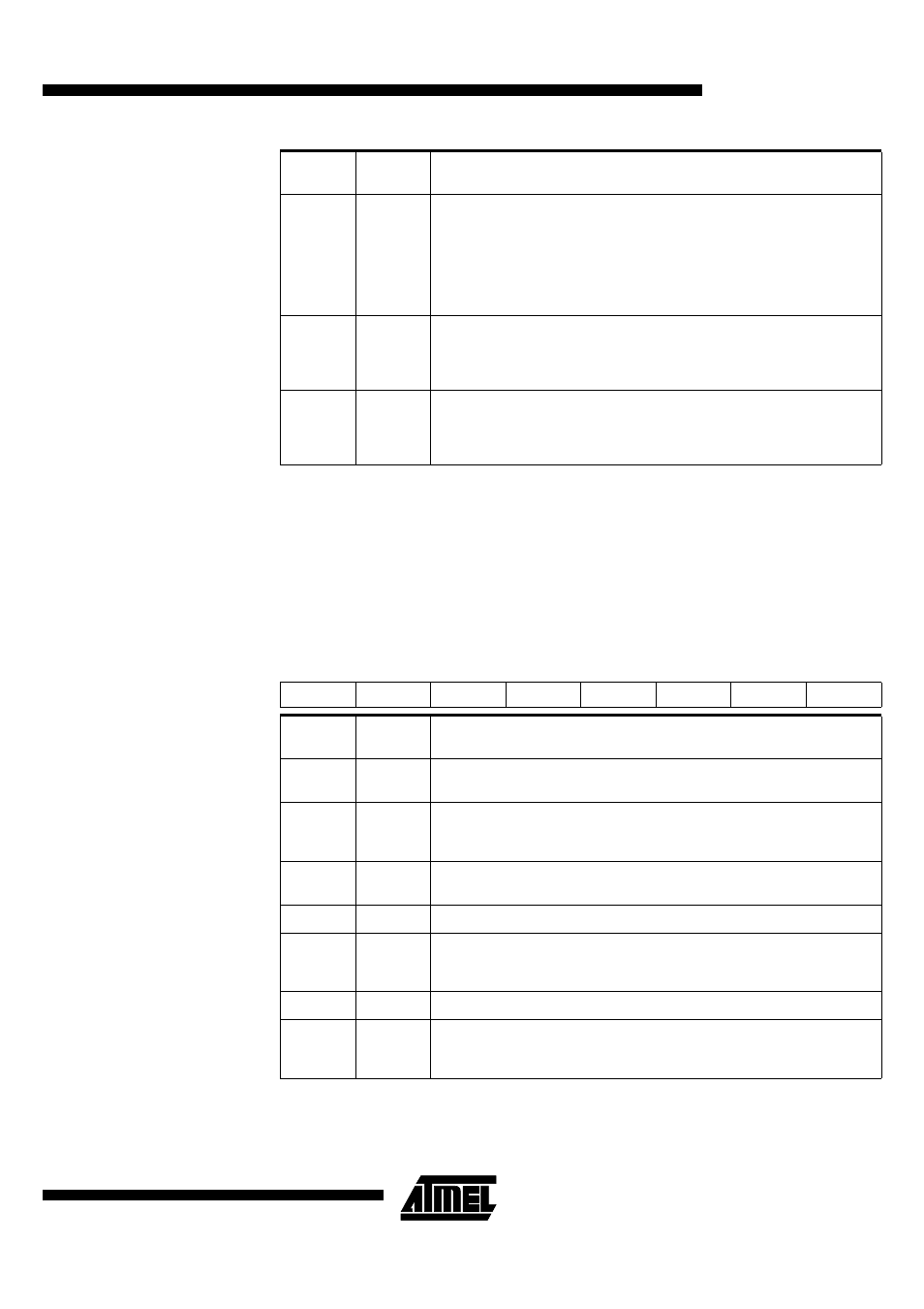
Table 5. AUXR1 Register
AUXR1 (S:A2h)
Auxiliary Control Register 1.
Reset Value= XXXX 00X0b
3-2
XRS1-0
ERAM size:
Accessible size of the ERAM
XRS1:0 ERAM size
0 0
256 bytes
0 1
512 bytes
1 0
768 bytes
1 1
1024 bytes (default)
1
EXTRAM
Internal/External RAM (00h - FFh)
access using MOVX @ Ri / @ DPTR
0 - Internal ERAM access using MOVX @ Ri / @ DPTR.
1 - External data memory access.
0
A0
Disable/Enable ALE)
0 - ALE is emitted at a constant rate of 1/6 the oscillator frequency (or 1/3 if X2
mode is used)
1 - ALE is active only during a MOVX or MOVC instruction.
Bit
Number
Bit
Mnemonic
Description
7
6
5
4
3
2
1
0
-
-
ENBOOT
-
GF3
0
-
DPS
Bit
Number
Bit
Mnemonic
Description
7-6
-
Reserved
The value read from these bits is indeterminate. Do not set these bits.
5
ENBOOT
Enable Boot Flash
Set this bit for map the boot flash between F800h -FFFFh
Clear this bit for disable boot flash.
4
-
Reserved
The value read from this bit is indeterminate. Do not set this bit.
3
GF3
General Purpose Flag 3.
2
0
Always Zero
This bit is stuck to logic 0 to allow INC AUXR1 instruction without affecting GF3
flag.
1
-
Reserved for Data Pointer Extension.
0
DPS
Data Pointer Select Bit
Set to select second dual data pointer: DPTR1.
Clear to select first dual data pointer: DPTR0.