Rainbow Electronics T89C51CC01 User Manual
Page 81
81
T89C51CC01
Rev. D – 17-Dec-01
15.9 Time Trigger
Communication (TTC)
and Message Stamping
The T89C51CC01 has a programmable 16-bit Timer (CANTIMH&CANTIML) for mes-
sage stamp and TTC.
This CAN Timer starts after the CAN controller is enabled by the ENA bit in the CANG-
CON register.
Two modes in the timer are implemented:
•
Time Trigger Communication:
–
Capture of this timer value in the CANTTCH & CANTTCL registers on Start
Of Frame (SOF) or End Of Frame (EOF), depending on the SYNCTTC bit in
the CANGCON register, when the network is configured in TTC by the TTC
bit in the CANGCON register.
Note:
In this mode, CAN only sends the frame once, even if an error occurs.
•
Message Stamping
–
Capture of this timer value in the CANSTMPH & CANSTMPL registers of the
message object which received or sent the frame.
–
All messages can be stamps.
–
The stamping of a received frame occurs when the RxOk flag is set.
–
The stamping of a sent frame occurs when the TxOk flag is set.
The CAN Timer works in a roll-over from FFFFh to 0000h which serves as a time base.
When the timer roll-over from FFFFh to 0000h, an interrupt is generated if the ETIM bit
in the interrupt enable register IEN1 is set.
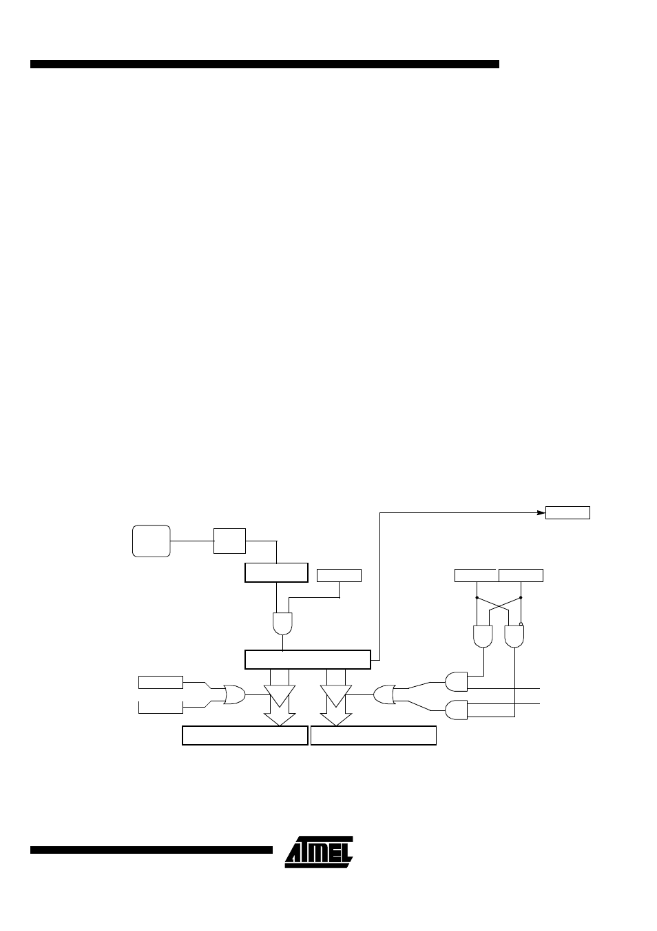
Figure 38. Block diagram of CAN Timer
EOF on CAN frame
ENA
CANGCON.1
CANTCON
RXOK i
CANSTCH.5
TXOK i
CANSTCH.4
÷
6
Fcan
CLOCK
SOF on CAN frame
TTC
CANGCON.5
SYNCTTC
CANGCON.4
CANTTCH & CANTTCL
CANSTMPH & CANSTMPL
CANTIMH & CANTIML
OVRTIM
CANGIT.5
When 0xFFFF to 0x0000