Sfr’s on-chip can controller registers, Message object window sfrs – Rainbow Electronics T89C51CC01 User Manual
Page 72
72
T89C51CC01
Rev. D – 17-Dec-01
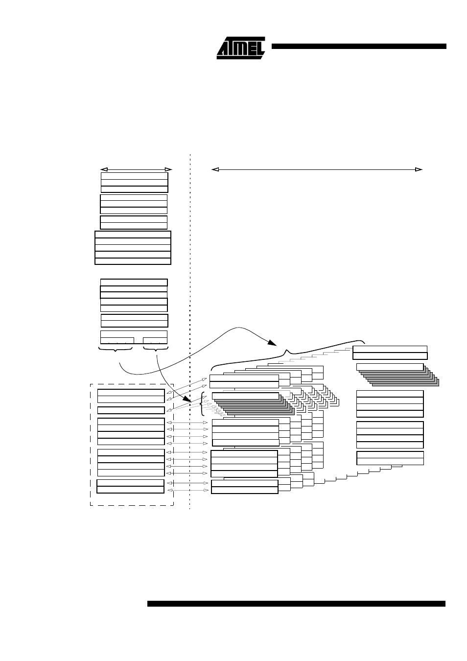
15.2 CAN Controller
Mailbox and Registers
Organization
The pagination allows management of the 321 registers including 300(15x20) bytes of
mailbox via 34 SFR’s.
All actions on the message object window SFRs apply to the corresponding message
object registers pointed by the message object number find in the Page message object
register (CANPAGE) as illustrate in Figure 31.
Figure 31. CAN Controller memory organization
Ch.14 - ID Tag - 1
Ch.14 - ID Tag - 2
Ch.14 - ID Tag - 4
Ch.14 - ID Tag - 3
Ch.14 - ID Mask - 1
Ch.14 - ID Mask - 2
Ch.14 - ID Mask - 4
Ch.14 - ID Mask - 3
Ch.14 - Message Data - byte 0
General Control
General Status
Bit Timing - 1
Bit Timing - 2
Bit Timing - 3
Enable Interrupt
Enable Interrupt message object - 1
Page message object
message object Status
message object Control & DLC
Message Data
ID Tag - 1
ID Tag - 2
ID Tag - 4
ID Tag - 3
ID Mask - 1
ID Mask - 2
ID Mask - 4
ID Mask - 3
message object 0 - Status
message object 0 - Control & DLC
Ch.0 - ID Tag - 1
Ch.0 - ID Tag - 2
Ch.0 - ID Tag - 4
Ch.0 - ID Tag - 3
Ch.0 - Message Data - byte 0
message object 14 - Status
message object 14 - Control & DLC
Enable Interrupt message object - 2
Status Interrupt message object - 1
Status Interrupt message object - 2
(message object number)
(Data offset)
SFR’s
on-chip CAN Controller registers
15 message objects
8 bytes
TimStmp High
TimStmp Low
Ch.0 - ID Mask- 1
Ch.0 - ID Mask- 2
Ch.0 - ID Mask - 4
Ch.0 - ID Mask- 3
CANTimer High
CANTimer Low
TimTTC High
TimTTC Low
TEC counter
REC counter
Timer Control
Enable message object - 1
Enable message object - 2
message object Window SFRs
Ch.0 TimStmp High
Ch.0 TimStmp Low
Ch.14 TimStmp High
Ch.14 TimStmp Low
General Interrupt