10-2 in case of ix, Assembly – Olympus IX2-DSU BX-DSU User Manual
Page 66
ASSEMBLY
/ Installation of visual mirror unit (front side)
II.
DSU
II .
8 - 1 2
Page
8-10-2 In case of IX
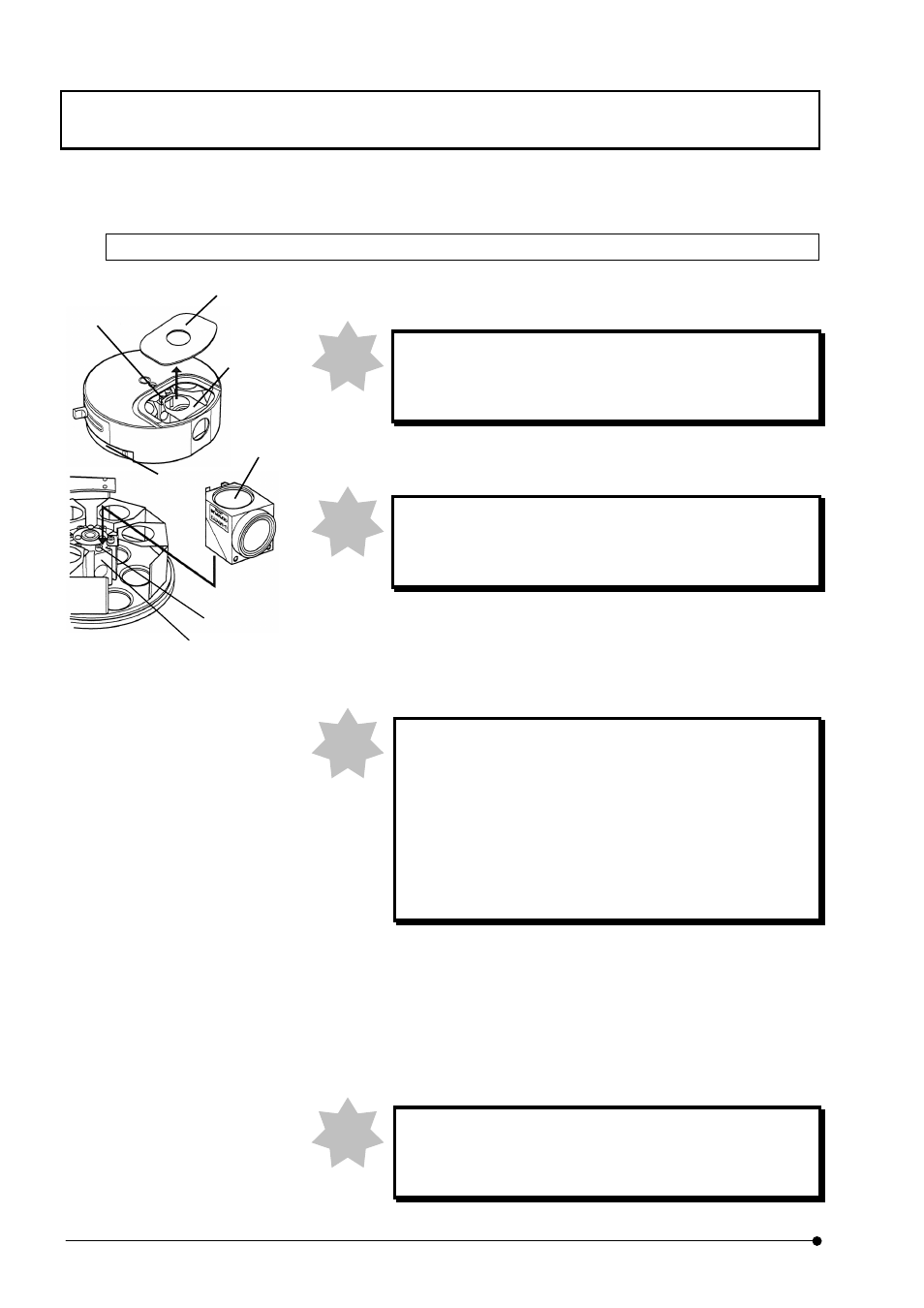
1.
Remove cover (1) that is sucked with magnet from mirror unit cassette.
When mirror units already exist inside the cassette, be
careful so as not to touch dichroic mirror or excitation filter
with your finger.
2. Turn turret (2) of mirror unit cassette manually and align mirror unit
mounting position with mirror unit mounting hole.
Reference mirror of adjustment completed is attached at
No.1 position. Do not change the position of this reference
mirror.
3.
Loosen fixing screw (3) of mirror unit mount dovetail for mirror unit cassette,
using dedicated the Allen screwdriver.
4. Displace dummy mirror unit (4) little by little circumferentially and pull it
towards outside of turret and detach it by pulling upward.
In case of reflected-light fluorescence observation, attach
dummy mirror unit for sure to the place where mirror unit is
not installed. In case of transmitting observation, dummy
mirror unit is not required. However, the fixing screw (3) for
mount dovetail should be tightened at the place where
dummy mirror unit is not installed. If this fixing screw is
loosened, head of screw may interfere when turret turns.
5. Insert mirror unit (5) into mirror unit mount dovetail (6) and push it until it
hits to dead end and then, tighten fixing screw (3), using dedicated the
Allen screwdriver.
6.
Attach turret cover (1), aligning it with well of mirror unit cover.
7. Insert identifying plate for mirror unit, corresponding to number of turret
that comes into light path into display pocket of microscope frame.
When display pocket of microscope frame is used for
indicator of objective lens, it cannot be used as indicator of
mirror unit.
Note
Note
Note
(1)
(3)
(4)
(2)
(3)
(6)
(5)
Note