Function sequence and led function display, C > on °c – M&C TechGroup ECS Operator's manual User Manual
Page 18
18
Gas sampling and gas conditioning technology
3-4.1-ME
The following steps should be carried out before initial start-up:
Connect the cooler unit to the mains power supply;
Check that the equipment is connected to the correct mains voltage, 115V or 230V, as shown on
the type plate!
Lead the status contacts for reporting of under- and over-temperature to the measuring station;
N O T E !
The status contacts must be connected to the external sample gas pump
or to a valve in the sample gas line to protect the entire analysis system
by immediately cutting off the gas supply in the event of error messages
from the cooler!
14.1
FUNCTION SEQUENCE AND LED FUNCTION DISPLAY
Three function display LEDs are provided to give a visualization of the function sequence during start-
up of the cooler. According to the type of installation, they are located either on the front panel or the
back panel of the cooler (Fig. 2). The top LED (red) indicates that the temperature set by the EC
automatic control electronics has been exceeded or has not been reached. The two-colour
(pink/green) LED in the middle shows that the cooler compressor is operating. The bottom red
function display LED gives an alarm if the temperature falls too low.
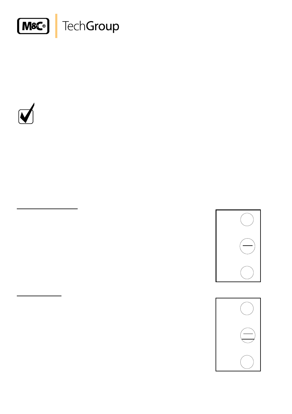
Switching the cooler on
As soon as there is a mains voltage, the top red LED lights up. This indicates
that the temperature of the cooler is above +8°C. The two-coloured LED in
the middle lights up as pink once the cooler compressor is in operation.
Normal operation
After around 30 minutes the cooler has been cooled down to a temperature
below +8°C. The top red LED goes out.
The status collector alarm contacts are deactivated and control the automatic
external release for gas measurement.
The cooler compressor is switched of as soon as the cooler stage reaches
the controlled temperature of +5°C. The middle LED lights up as green.
The cooler compressor will be alternately switched on and off by the EC
automatic control electronics in a load-dependent cycle. The middle LED will
alternately light up as pink and green (normal operating functions).
°C >
ON
°C <
red
pink
green
°C >
ON
°C <
pink
green